What is Feedback? What is Feedback in Amplifier? Feedback: Feedback is a phenomenon of universal importance and has, therefore, entered the general vocabulary. Thus, consider the following situation: you are an officer. You have instructed a subordinate to do a certain job. After some time, the person informs you about the state of job, whether satisfactorily completed or there are some difficulties. Thus, information constitutes the feedback. You definitely want this feedback to ensure that the job was been done; if not then what corrective measures are to be adopted.…
Read MoreDelay Starter using 556 Dual Timer IC
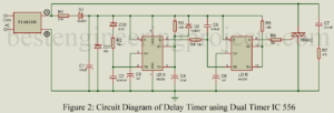
Delay Starter using 556 Dual Timer IC: The systems using compressors such as air conditioners, refrigerators, freezers etc. are to be cared for properly to avoid damage to the compressor due to fluctuations in the line voltage. After switch off, if is switched on immediately, the compressor may fail. This is avoided by connecting it through DOL (direct on line) starter. The DOL starter trips the supply as the power fails. When the power resumes, the starter has to be started manually. But the presence of an operator round the…
Read MoreMaximum Collector Efficiency of Class A Amplifier
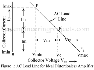
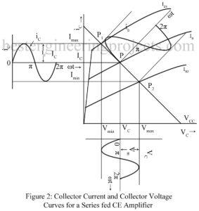
Maximum Collector Circuit Efficiency of Class A Amplifier Conversion Efficiency An amplifier draws a.c. power from dc supply (collector supply VCC in CE amplifier) and converts a part of it into useful a.c. power delivered to the load impedance. The ratio of the a.c. output power to the d.c. power from the supply source in the output is called the conversion efficiency, also called collector circuit efficiency in the case of CE amplifier and is denoted by Greek letter . Thus, ……(1) For present analysis, we assume a resistance…
Read MoreBattery Level Indicator
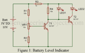
The circuit ‘Battery Level Indicator’ is simple, cheap, and compact. It can be used in emergency lights and other power supply circuits. We are using this simple circuit ‘battery level indicator’ for over a year and has found it works well in emergency light as well as battery charger circuit. We already indicate various battery voltage states using IC, this time we come with a little different concept and circuit for battery indication. Other battery level circuits posted in bestengineeringprojects.com Battery Status indicator Circuit 10 Level Battery Charge Indicator Circuit…
Read MoreTransformer Coupled Audio Power Amplifier
Transformer Coupled Audio Power Amplifier: Untuned large signal amplifier (power amplifier) of class AB and B type invariably use transformer coupled stages while those of class A type also generally use transformer coupled stage. RC coupled stages are not used because the quiescent current flawing through the load resistor results in large wastage of dc power in it. This dc power dissipated in the load resistor does not contribute to the useful ac output power. Further flow of dc current through the output device is not desirable. Hence it is…
Read MoreSingle Phase Preventer with Under/Over Voltage Cutout
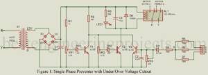
For a 3-phase induction motor, all three phases of the supply must be present. If any of the phases is missing, or a fuse is blown, the motor will continue to run with two phases only. But in that case, it will draw a very large current, and it may burn unless switched off immediately. To solve this problem the project “Single Phase Preventer with Under/Over Voltage Cutout” is posted here. For the protection of a three-phase induction motor, various types of starters are utilized. But the problem with Starters…
Read MoreHarmonic Distortion in Amplifier
Second Harmonic Distortion in Amplifier In the graphical analysis given in the preceding article, the amplifying device is assumed to be preferable linear. Thus, we have assumed the output characteristics to be linear, parallel and equi-spaced for equal increments of the parameter. Then the corresponding dynamic transfer characteristic is also linear. Thus, linear amplification requires dynamic transfer characteristic to be linear. In practice, however, the dynamic transfer characteristic is never truly linear. For optimum linearity of amplification using the available amplifying device, we operate over such small region of dynamic…
Read MoreLarge Signal Amplifier | Power Amplifier
Large Signal Amplifier | Power Amplifier: In a multistage amplifier, first stage or the input stage and the intermediate stage are usually small signal class A amplifier stage while the last stage (the output stage) or sometimes last two stage are large signal amplifier (power amplifier) stage. Small signal amplifier stages serve to amplify the weak input signal to a sufficient large value to drive the final stage. The output stage generally feeds a transducer such as CR Tube, a loud speaker, a servo-control motor etc. the large signal amplifier…
Read MoreLight Sensor Switch Circuit using LDR and 741 IC
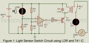
There are some projects from which every electronics hobbyist starts their journey toward electronics. Same like another hobbyist I had also started my journey of electronics projects by making a very basic project called a light-operated switch using a single transistor. After six long years of the journey today, I had again come up with a basic project which will surely help beginners. The project posted here is of Light Sensor Switch Circuit using LDR and 741 IC. The project switches on the electrical bulb according to the intensity of…
Read MoreTransformer Coupled CE Amplifier
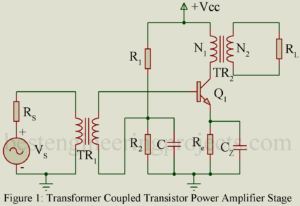
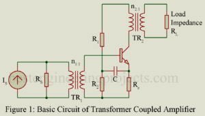
Figure 1 gives the basic circuit of a transformer coupled CE amplifier stage. In figure 1, a current source Is having shunt source resistance Rs drives the amplifier through a transformer TR1. Load resistance RL is fed from the collector output circuit through a transformer TR2. A transformer coupled CE amplifier finds following applications: As input stage of a multistage simplified and usually driven by a microphone. As output stage feeding the load impedance and As intermediate stage Transformer coupling permits impedance matching thereby resulting in greater power gain. The…
Read More
