Second Harmonic Distortion in Amplifier
In the graphical analysis given in the preceding article, the amplifying device is assumed to be preferable linear. Thus, we have assumed the output characteristics to be linear, parallel and equi-spaced for equal increments of the parameter. Then the corresponding dynamic transfer characteristic is also linear. Thus, linear amplification requires dynamic transfer characteristic to be linear.
In practice, however, the dynamic transfer characteristic is never truly linear. For optimum linearity of amplification using the available amplifying device, we operate over such small region of dynamic transfer characteristic which is essentially linear. In case, we operate over nonlinear region of the dynamic transfer characteristic, the output signal waveform differs from the input signal waveform. Such a distortion is called nonlinear distortion or amplitude distortion.
When nonlinear distortion is present, the output current/voltage contains components of frequencies which are harmonics of the input signal frequency. Harmonic distortion is said to be present. They may be present second, third and higher order, harmonic components. However, the most prominent among these harmonic components is the second harmonic component. We, therefore, proceed to investigate the magnitude of this distortion. We assume that the dynamic characteristic with respect to the quiescent operating point P may be represented by a parabola rather than a straight line. With linear dynamic characteristics, the output a.c. current ic is linearly related with the input excitation ib. Thus,
 …..(1)
Where G1 is a constant.
However, with parabolic dynamic characteristic, a square term gets added and ic is given by,
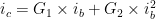 …..(2)
We assume sinusoidal input excitation. Thus,
 …..(3)
Combining equations 2 and 3 we get,
 ……(4)
……(4)
But
 ……(5)
……(5)
Hence instantaneous total collector current ic may be expressed as,
 ……(6)
……(6)
Equation 6 shows that application of a sinusoidal signal on a parabolic dynamic curve results in (i) terms  of the same frequency as the input (ii) increase of d.c. current from IC to (IC + B0) i.e. rectification takes place and (iii) a second harmonic term
  .
.
For a given load resistor, amplitude of B0, B1 and B2 may be easily determined from either the static or the dynamic characteristic. Thus, from figure, we find that,
At  ……(7a)
At  ……(7b)
At  ……..(7c)
On substituting the value as given by equation (7) into equation (6) we get,
 ……..(8a)
 …..(8b)
 ……(8c)
From this set of three equations (8) we determined the three unknown B0, B1 and B2 in term of Imax, Imin and IC.
Thus from equations (8b), B0 = B2 ……..(9)
On subtracting equation (8c) from equation (8a) we get,
 ……(10)
Substituting this value of B1 as given by Equation (10) we get,
 ……..(11)
The second harmonic distortion D2 is defined as,
 …….(12)
Quantities Imax, Imin and IC may be obtained directly from the characteristic curves of the transistor and the load line.
In case of a linear dynamic characteristic, (Imax + Imin) = 2 IC and hence B2 = B0 = 0. However, if the dynamic characteristic is of the parabolic form as given by equation (12) and the input signal contains terms of two frequencies  and
and  , then the output will consist of (i) a dc term (ii) components of frequencies , ,
  and
and  (iii) components of frequencies
  and
and  . These sum and difference frequencies constitute the so-called intermodulation frequencies or the combination frequencies.
Higher Order Harmonic Terms
For small swing of input signal, assumption of parabolic dynamic characteristic is valid and only second harmonic need be considered. However, in a power amplifier with large input signal swing, the dynamic transfer characteristic is not confined to parabolic form and hence the a.c. collector current is given by a power series of the following form:
 ……..(13)
We assume that input signal (base current) is a pure cosine function given below.
 ……..(14)
On combining equations (14) and (13) we get,

The value of coefficients B0, B1, B2 and B3 may be evaluated from the graphical analysis.
Harmonic distortion are then defined as,
……..(15a)
 ……..(15b)
 ……..(15c)
Power Output In the presence of harmonic distortion, the power delivered at the fundamental frequency is,
 ……..(16)
Total power output is,

 ……(17)
Or  …….(18)
Where D is the total harmonic distortion factor and is defined as,
 …….(19)
With 10% total harmonic distortion,
![P = [1 (0.1)^2]P_1 = 1.01 P_1](https://s0.wp.com/latex.php?latex=P+%3D+%5B1+%280.1%29%5E2%5DP_1+%3D+1.01+P_1&bg=ffffff&fg=000&s=0&c=20201002) ……(20)
……(20)
Thus, when total harmonic distortion is 10%, total output power has increased by only 1%. Hence up-to 10% total harmonic distortion, we may use the fundamental power P1 in place of total power P without causing appreciable error. However, considerable error results if we use
In calculating the output power.