Introduction:
In the world of electronics, different types of waveforms are essential for testing various circuits. A sine wave signal is commonly used for assessing linear circuits such as amplifiers and filters. In contrast, a square wave input becomes crucial when testing digital circuits like flip-flops, counters, and registers. In this article, we’ll delve into constructing and operating an audio function generator utilizing the specialized integrated circuit, ICL8038. Notably, this audio function generator circuit offers not only sine and square waves but also triangle waves.
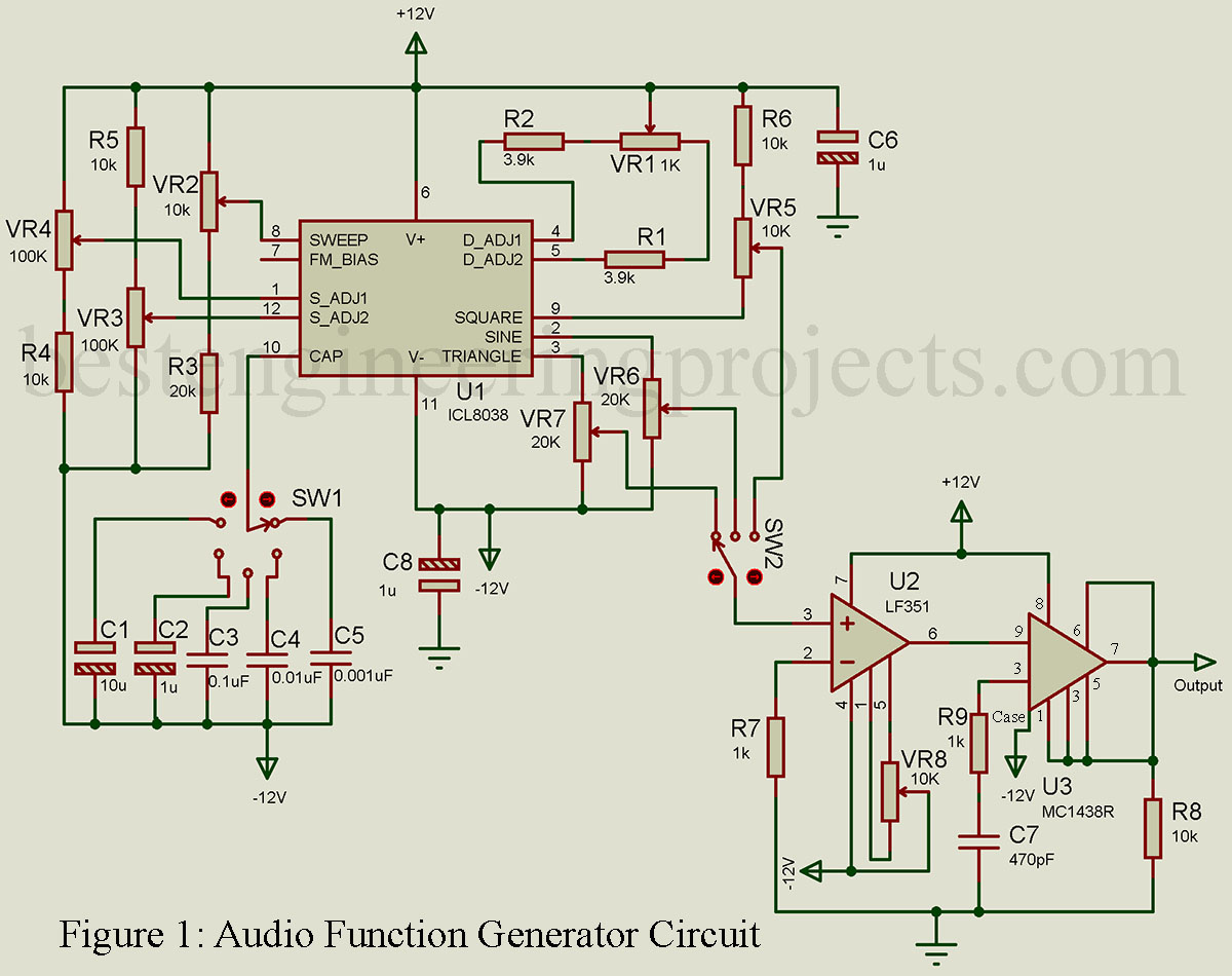
Circuit Description and Operation of Audio Function Generator Circuit:
Let’s explore how the ICL8038 can serve as an audio function generator. The circuit depicted in Figure 1, is capable of generating sine waves, square waves, and triangle waves, covering a frequency range from less than 20 Hz to over 100 kHz. However, it’s worth noting that at around 100 kHz, the quality of the output waveforms begins to deteriorate. Sine and triangle waves may distort, and the square wave transforms into a pulse waveform with a duty cycle of less than 50%.
Despite this limitation, the function generator presented in Figure 1 maintains high laboratory standards and finds applications in calibration and critical design scenarios. It’s also a valuable tool for novice designers and hobbyists, given its simplicity and cost-effectiveness.
Waveform Selection and Frequency Control:
The circuit in Figure 1 employs switch SW2 to select the desired output waveform. Once the output waveform is chosen, frequency select switch SW1 allows you to pick an appropriate frequency range. The specific frequency is then fine-tuned by adjusting potentiometer R4, which varies the potential at pin 8 from +VCC to +VCC/3 concerning ground, thereby altering the output waveform’s frequency.
Potentiometer R3 serves to adjust the duty cycle of the square wave output, particularly at higher frequencies. Additionally, potentiometers R7 and R9, whose wipers are connected to pins 1 and 12 respectively, are adjusted to minimize sine wave distortion.
Square Wave Output Control:
Pin 9 provides an uncommitted square wave output, which can be tailored for TTL compatibility by connecting it through a pull-up resistor to a +5 V supply if needed. In the circuit, pin 9 is connected through resistor R10 and potentiometer R11 to +12 V. R11 allows you to adjust the square wave’s output amplitude to your desired level.
Triangle and Sine Wave Adjustments:
The triangle wave output is available at pin 3 with an amplitude of (0.33)(±12 V) = ±3.96 V. Potentiometer R12 is employed to fine-tune the amplitude of the triangle wave. Similarly, the sine wave output, available at pin 2, has an initial amplitude of (0.22)(±12 V) = ±2.64 V, which can be customized using potentiometer R13.
Output Stage Enhancement:
Switch SW2 facilitates the selection of one of the three output waveforms, which is then routed to the output stage, consisting of an operational amplifier (op-amp) and a power booster.
This output stage serves two critical functions:
- It provides a low output impedance and
- It enhances the output power drive capability of the ICL8038.
Without the output stage, the output resistance of the triangular and square waves is 200 Ω, while that of the sine wave is 1 kΩ. The output stage, configured as a non-inverting amplifier, significantly reduces the output resistance.
Inside the op-amp’s feedback loop, the power booster MC1438R (or BB3553) is employed, improving the ICL8038’s output drive capability without compromising the op-amp’s characteristics. The chosen op-amp for this application is the LF351, boasting a slew rate of 13 V/µs and a unity gain bandwidth of 4 MHz. It operates as a non-inverting amplifier with a gain of 11.
Offset Voltage Adjustment:
For smaller amplitude output AC signals, it might be necessary to initially eliminate the output offset voltage. This can be achieved by adjusting the offset null circuitry, specifically potentiometer R14 on the LF351 op-amp.
Following this guide, you can construct an audio function generator based on the ICL8038 integrated circuit, providing versatile waveform outputs for your electronic testing needs.
Component list of Audio Function Generator Circuit
Resistors (all ¼-watt, ± 5% Carbon)
R1, R2 = 3.9 kΩ
R3 = 1kΩ Potentiometer
R4, R11, R14 = 10 kΩ Potentiometer
R5 = 20 kΩ
R6, R8, R10, R15 = 10 kΩ
R7, R9 = 100 kΩ Potentiometer
R12, R13 = 20 kΩ Potentiometer
R16, R17 = 1kΩ
Capacitors
C1 = 10µF
C2, C6, C7 = 1µF
C3 = 0.1µF
C4 = 0.01µF
C5 = 0.001µF
C8 = 470 pF
Semiconductors
IC1 = ICL8038 Function generator
IC2 = LF351 op-amp
IC3 = MC1438R power booster
Miscellaneous
SW1 = Five-position switch
SW2 = Three-position switch