Phase Shift Keying (PSK) is an exceptionally efficient method of data modulation known for its remarkable reliability. In this article, we delve into the intricacies of PSK modulation and its diverse applications.
Understanding Phase Shift Keying (PSK) Modulation
One of the most efficient methods for data modulation is phase shift keying (PSK). PSK systems provide a low probability of error. The incoming data causes the phase of the carrier to phase-shift a defined amount.
The Mathematical Expression of PSK
This relationship is expressed as:
![V_0(t) = V sin[\omega_c(t) + \dfrac{2\pi (i-1)}{M}]](https://s0.wp.com/latex.php?latex=V_0%28t%29+%3D+V+sin%5B%5Comega_c%28t%29+%2B+%5Cdfrac%7B2%5Cpi+%28i-1%29%7D%7BM%7D%5D&bg=ffffff&fg=000&s=0&c=20201002) …..(1)
…..(1)
where: i= 1, 2, .. .,M
M = 2N, number of allowable phase states
N= the number of data bits needed to specify the phase state
 = angular velocity of the carrier.
The variant of PSK Signal
There are many versions of the PSK signal. Three common versions are shown in Table 1.
| Binary Phase Shift Keying-BPSK | M = 2 | N = 1 |
| Quadrature Phase Shift Keying – QPSK | M = 4 | N = 2 |
| 8PSK | M = 8 | N = 3 |
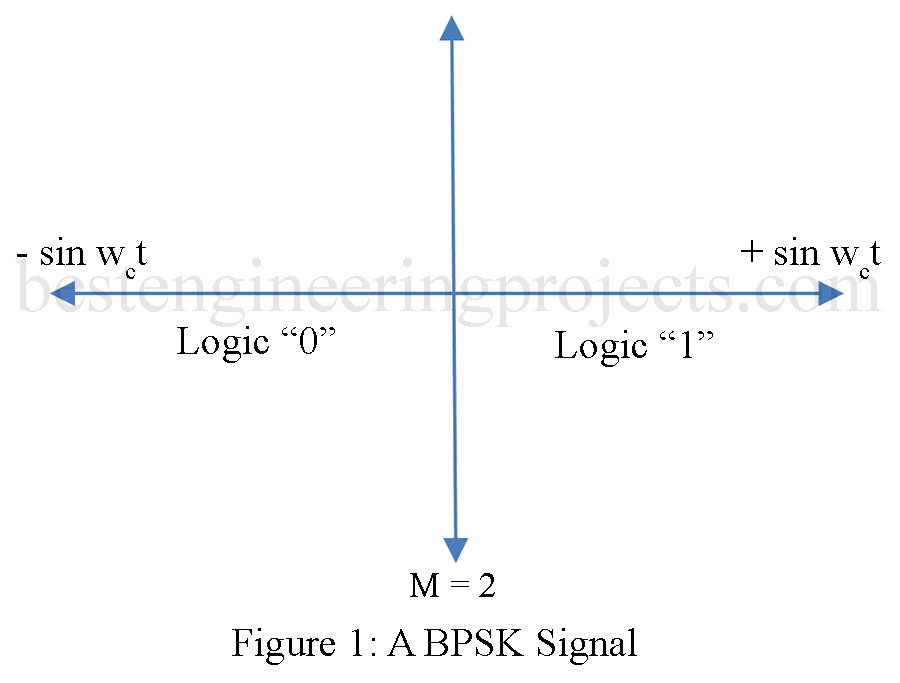
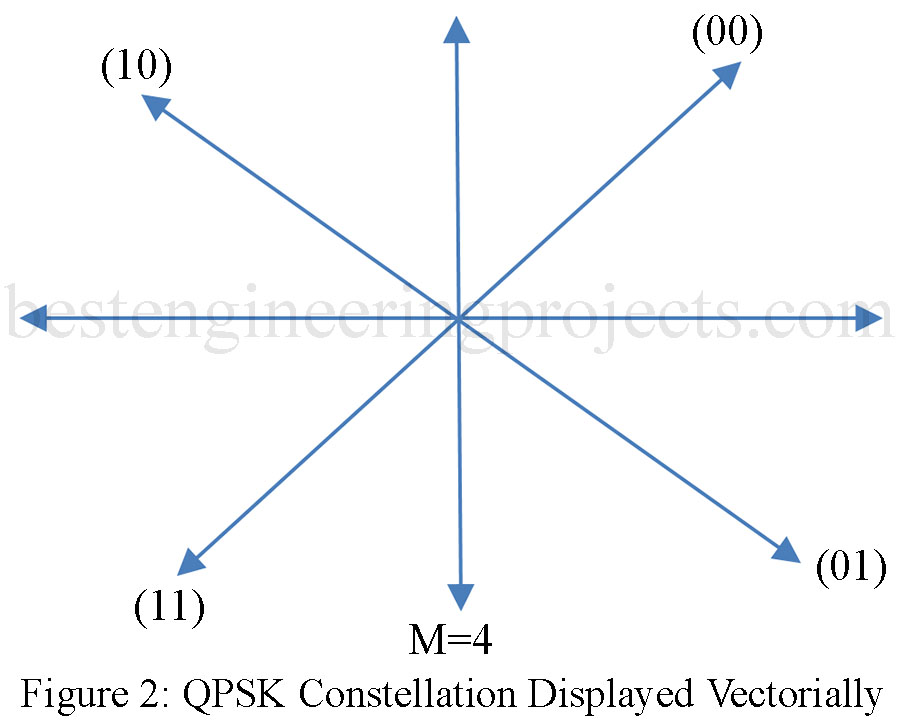
With M (the number of allowable phase states) greater than four the systems are referred to as M-ary systems, and the output signal is called a constellation. In a binary shift keying (BPSK) signal, the phase of the carrier will shift by 180° (i.e., +/- sin t). For a quadrature phase shift keying (QPSK) signal the phase changes 90° for each possible state. A diagram showing both a BPSK and QPSK constellation is provided in Figures 1 and 2.
Binary Phase Shift Keying
It has been defined that for a BPSK signal, M = 2 and N = 1. The  vector provides the logical “1” and the
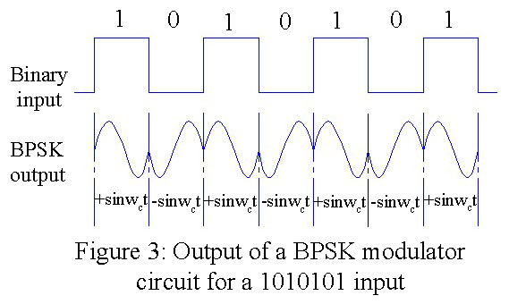
  vector provides the logical “0” as shown in Fig. 1. The BPSK signal does not require that the frequency of the carrier be shifted as with the FSK system. Instead, the carrier is directly phase-modulated, meaning that the phase of the carrier is shifted by the incoming binary data. This relationship is shown in Fig. 3 for an alternating pattern of 1’s and 0’s.
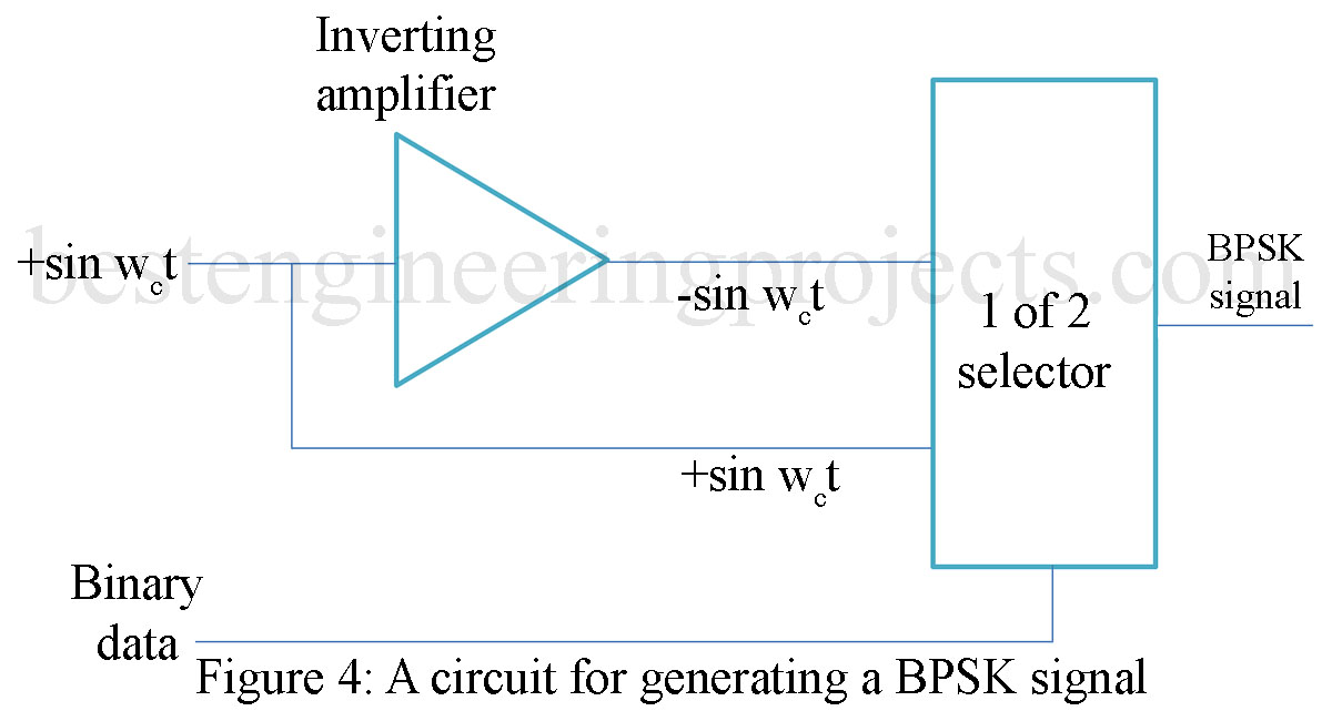
Generating BPSK Signals
The generation of the BPSK signal can be accomplished in many ways. A block diagram of a simple method is shown in Fig. 4. The carrier frequency is phase-shifted 180°. The + and – values are then fed to a 1 of 2 selector circuit, which is driven by the binary data. If the binary data is a 1, then the output is . If the binary – input data is a 0, then the signal is selected for the output. The actual devices selected for performing this operation are dependent on the binary input data rate and the transmit carrier frequency.
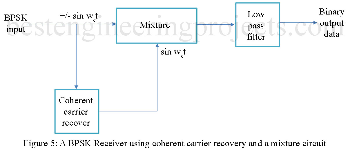
Receiving and Demodulating BPSK
A BPSK receiver requires that the phase shift be detected. One possible way of constructing a BPSK receiver is by using a mixer circuit. The received BPSK signal is fed into the mixer circuit. The other input to the mixer circuit is driven by a reference oscillator synchronized to  . This is referred to as coherent carrier recovery. The recovered carrier frequency is mixed with the BPSK input signal to provide the demodulated binary output data. A block diagram of the receive circuit is provided in Fig. 5. Mathematically, the BPSK receiver shown in Fig. 5 can provide a 1 and a 0 as shown:
![1 Output = [sin(\omega_c t)][sin(\omega_c t)] = sin^2(\omega_c t)](https://s0.wp.com/latex.php?latex=1+Output+%3D+%5Bsin%28%5Comega_c+t%29%5D%5Bsin%28%5Comega_c+t%29%5D+%3D+sin%5E2%28%5Comega_c+t%29&bg=ffffff&fg=000&s=0&c=20201002) and by trig identity
and by trig identity ![sin^2A = \dfrac{1}{2}[1-cos2A].</span></p> <p><span style="font-weight: 400;">Therefore [latex]1 output = \dfrac{1}{2}-\dfrac{1}{2}[cos(2\omega_c t)]](https://s0.wp.com/latex.php?latex=sin%5E2A+%3D+%5Cdfrac%7B1%7D%7B2%7D%5B1-cos2A%5D.%3C%2Fspan%3E%3C%2Fp%3E+%3Cp%3E%3Cspan+style%3D%22font-weight%3A+400%3B%22%3ETherefore+%5Blatex%5D1+output+%3D+%5Cdfrac%7B1%7D%7B2%7D-%5Cdfrac%7B1%7D%7B2%7D%5Bcos%282%5Comega_c+t%29%5D&bg=ffffff&fg=000&s=0&c=20201002)
The ![</span><span style="font-weight: 400;">[cos(2\omega_c t)]](https://s0.wp.com/latex.php?latex=%3C%2Fspan%3E%3Cspan+style%3D%22font-weight%3A+400%3B%22%3E%5Bcos%282%5Comega_c+t%29%5D&bg=ffffff&fg=000&s=0&c=20201002) term is filtered out by the low-pass filter shown in Figure 10.3. This leaves
term is filtered out by the low-pass filter shown in Figure 10.3. This leaves

Similarly, the analysis will show
![0 Output = </span><span style="font-weight: 400;">[-sin(\omega_c t)][sin(\omega_c t)]](https://s0.wp.com/latex.php?latex=0+Output+%3D+%3C%2Fspan%3E%3Cspan+style%3D%22font-weight%3A+400%3B%22%3E%5B-sin%28%5Comega_c+t%29%5D%5Bsin%28%5Comega_c+t%29%5D&bg=ffffff&fg=000&s=0&c=20201002)


The  represent dc values that correspond to the 1 and 0 binary values. The values can be conditioned for the appropriate input level for the receive digital system.
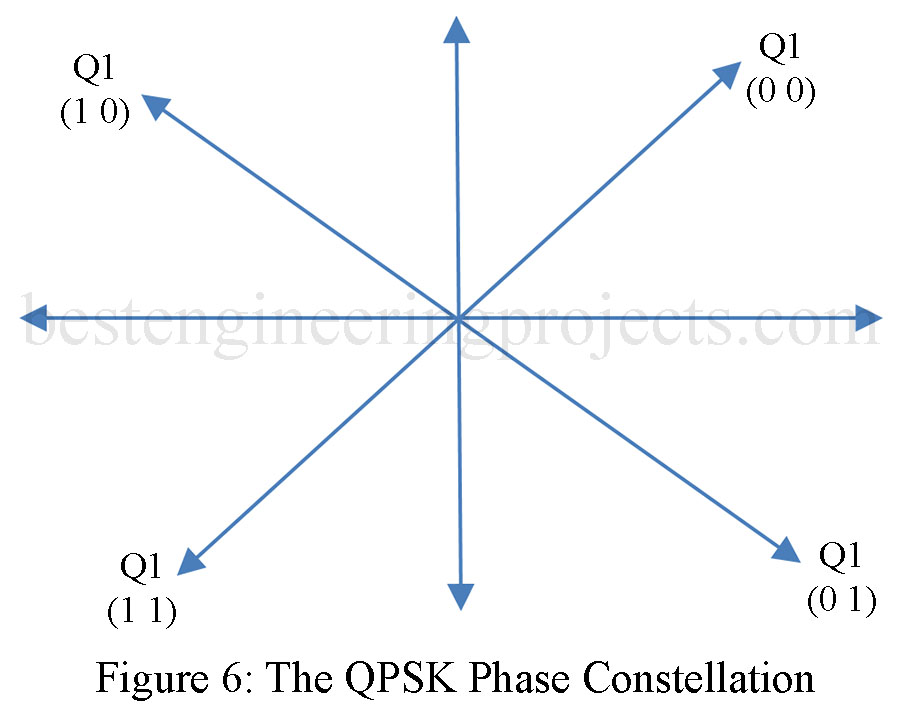
Quadrature Phase Shift Keying (QPSK)
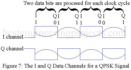
The QPSK constellation provides four vectors for representing the binary data. The savings by transmitting this way are in the reduced bandwidth requirement. The QPSK system uses two data channels. These are identified as the I and Q channels. Each channel contributes to the direction of the vector within the phase constellation. The four possible values for I and Q are shown in Fig. 6.
The BPSK signal requires a  whereas the QPSK signal will only require
  for each channel. The quantity
  refers to the frequency of each of the original bits in the data. With QPSK transmission, data bandwidth compression is realized. This means that more data are being compressed into the same available bandwidth. This relationship is shown pictorially in Fig. 7.