Communication is an essential part of our daily life. The project; “Laser-Based Communication Link” allows people at a distance of around 500 meters to communicate wirelessly through a laser. Various other laser-based projects posted on bestengineeringprojects.com are:-
(a) Speech Communication using Laser
(c) Laser Voice Transmitter Circuit
The project unlike other wireless media uses laser light from the transmitter torch as a carrier instead of RF signals used in the conventional system. At the receiver end, the phototransistor should be aligned in a line of sight position such that the laser beam from the torch falls perfectly on it. However, communication is not possible if there is any obstacle in the path of the beam and no sound will be heard at the receiver end.
The transmitter circuit of the Laser-Based Communication Link
The construction of this project is very much simple. There are two sections; transmitter and receiver section. As shown in figure 1, a condenser microphone transistor amplifier BC548 (T1) followed by an op-amp stage built around μA741 (IC1) completes the transmitter portion. A potmeter (1Mega-ohm) VR1 is used to adjust the gain of the op-amp as required in the project.

Another transistor BD139 (T2) takes the output from IC1 as the input signal through the base and then produces the modulated laser beam signal at its output terminal.
The transmitter circuit should be powered by a 9V supply, however, we can directly connect the laser torch (3V) to the emitter terminal of the transistor T2 after removing the battery. Similarly, the spring-loaded lead projected from inside the torch can be grounded.
The audio input is received by the mic incorporated in the project. With the help of a coupling capacitor C, the audio signal from the mic is fed to the transistor T1. There the signal is amplified to some extent and is passed towards the IC1 through another coupling capacitor C2 from further amplification. Then the amplified audio signal is sent to the transistor T2. It modulates the power to the LED and places the audio onto the light beam.
In this project, a potmeter VR1 acts as a gain adjusting tool for IC. For effective and noise-free results, capacitors; C3, C4, and a resistor R7 are used as power filters. Few other resistors are included to limit the amount of voltage supplied to the particular part of the circuit.
Receiver Circuit of Laser-Based Communication Link
Talking about the other half of the project, which is the receiving portion, comprises a photo-sensitive transistor; T3. The laser beam passed from the transmitter laser torch is received by T3 It produces a signal in correspondence to the light signal received from the LED transmitter circuit.
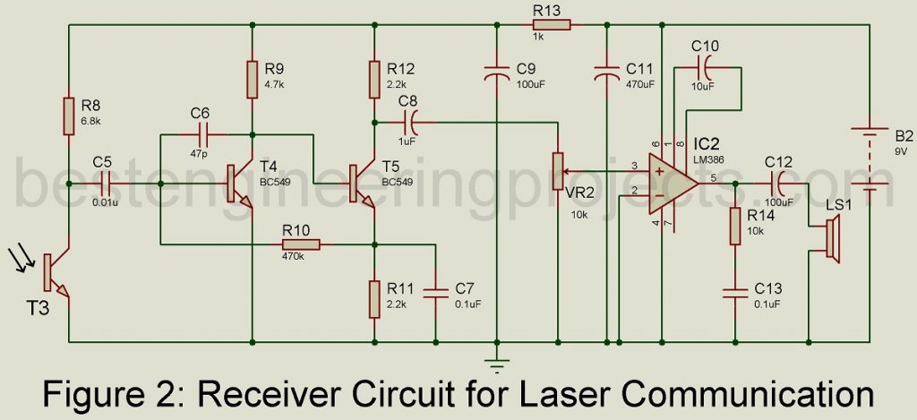
Hence, the signal is demodulated and received at this end. Capacitor C5 couples the demodulated signal to transistor T4 and T5 which produce the amplified version of the received signal. And, then the signal is coupled through C8 to VR2. Potmeter VR2 is employed to adjust the volume level of the signal for IC2. In IC2, the signal is again amplified and it drives the speaker; LS1.
Take necessary precautions like placing the photo-transistor away from the AC light sources like bulbs to eliminate the risk of developing hum noise in the speaker. The sunray shouldn’t fall directly on the sensor, but the reflected sunlight does not harm the circuit.
PARTS LIST OF LASER BASED COMMUNICATION LINK
| Resistors (all ¼-watt, ± 5% Carbon) |
| R1, R3 = 8.2 KΩ
R2 = 1.8 KΩ R4 = 10 KΩ R5, R6 = 15 KΩ R7 = 82 Ω R8 = 6.8 KΩ R9 = 4.7 KΩ R10 = 470 KΩ R11, R12 = 2.2 KΩ R13 = 1 KΩ R14 = 10 Ω VR1 = 1 MΩ VR2 = 10 KΩ |
| Capacitors |
| C1, C8 = 1 µF, 16V (Electrolytic Capacitor)
C2, C7, C13 = 0.1 µF (Ceramic Capacitor) C3 = 470 µF, 16V (Electrolytic Capacitor) C4 = 1000 µF, 16V (Electrolytic Capacitor) C5 = 0.01 µF (Ceramic Capacitor) C6 = 47 pF (Ceramic Capacitor) C9, C12 = 100 µF, 16V (Electrolytic Capacitor) C10 = 10 µF, 16V (Electrolytic Capacitor) C11 = 470 µF, 16V (Electrolytic Capacitor) |
| Semiconductors |
| IC1 = LM741 (Operational Amplifier IC)
IC2 = LM386 (low power Audio Amplifier) T1 = BC548 (General-Purpose NPN Bipolar Junction Transistor) T2 = BD139 (Complementary Low Voltage Transistor) T3 = 2N5777 or L14F1 (Photo Transistor) T4, T5 = BC549 (General-Purpose NPN Bipolar Junction Transistor) LED1 = 3 Volts Laser Torch |
| Miscellaneous |
| MIC1 = Condenser Microphone
LS1 = 0.5W, 8Ω Speaker |
where will the third pin(base) of the photo transistor(L14F1) go.
The base of transistor L14f1 should be left unconnected.