In electronics, Arduino has reshaped how we tinker with technology. Voltage measurement is a core aspect, but dealing with AC voltage adds complexity, especially without a transformer. Usually, transformers isolate high AC voltages for measurement. But when space or components are limited, Arduino offers an alternative. In this article, we’ll unravel measuring AC voltage using Arduino without the bulky transformer.
Component Requirements for AC Voltage Measurement using Arduino without Transformer
Arduino Board x 1
Grove- AC Voltage Sensor x 1
I2C LCD x 1
Circuit Description of AC Voltage Measurement using Arduino without Transformer
Introducing the versatile Grove AC Voltage Sensor, a must-have for your DIY energy metering activities, providing precise AC voltage measurements. Its adjustable gain feature allows seamless adaptation to different voltage inputs, whether you’re working with 120V or 240V AC. Compatibility is a draft, as it effortlessly interfaces with a diverse array of development boards, utilizing its Analog output.
It handles those unexpected voltage surges when high-power devices run. This sensor excels at capturing these changes with pinpoint accuracy, delivering consistent and reliable data on each case. At the heart of this capability lies the effective MCP6002 IC, promising not only accuracy but also consistent performance, especially with its Analog output capabilities.
One of the most appealing aspects of the Grove AC Voltage Sensor is its simplicity. Designed with user-friendliness in mind, it seamlessly integrates into your projects, requiring nothing more than a simple plug-and-play setup.
The circuit setup couldn’t be simpler, and it’s right there in the circuit diagram. The output from the Grove AC voltage sensor is analog, so we connect it to one of the analog pins on the Arduino. In this case, we’re using the A0 pin to read the sensor’s value. We also make sure to hook up the VCC and GND pins of the sensor to the +5V and GND pins on the Arduino board.

Now, for our display, we’ve gone with an I2C LCD, which is a smart move for streamlined communication. To get this LCD working, we need to connect its SDA and SCL pins to the I2C pins on the Arduino UNO/NANO, which, as you probably know, are the A4 and A5 pins. And, of course, we power the LCD by connecting its power supply pin to the +5V and GND pins on the Arduino.
But here’s where it gets even more interesting. We’ve got a potentiometer on the Grove sensor. This lets us play with the gain, making it adjustable to fit different input voltages. It’s like having a volume knob for your sensor’s sensitivity! This feature really kicks up the circuit’s versatility, allowing us to fine-tune things for different situations.
Software code
The software is created using the Arduino programming language, a familiar domain for anyone working in C/C++, and we compile it using the Arduino IDE. In this setup, we rely on two crucial libraries: one dedicated to handling the LCD, and the other precisely measuring voltage. If you’re looking to get your hands on the voltage measurement library, simply follow the link provided.
MCMVVoltSense Library Github Link
Once the library is installed, it’s time to roll up our sleeves and get practical. Open up the example code. For code go to example and search for MCMVoltSense and then open “VoltageSensing”.
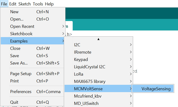
Figure 2: Example Code of AC voltage Measurement using Arduino
The software code is very simple and straightforward it took the Input pin, calibration value, and phase shift value as input, with this parameter it measures the input voltage and displays the voltage over the serial monitor.
|
1 2 3 4 5 6 7 8 9 10 11 12 13 14 15 |
#include "MCMVoltSense.h" // Include MCM Volt Sense Library MCMmeter meter; // Create an instance void setup() { Serial.begin(115200); meter.VoltageStp(A1, 523.56, 1.7); // Voltage: input pin, calibration, phase_shift } void loop() { meter.analogVoltage(40,2000); // Measure the AC voltage. Arguments = (# of AC cycles, timeout) float Vrms = meter.Vrms; // Save the RMS Voltage into a variable. Serial.print("Voltage: "); Serial.print(Vrms,2); Serial.println(" V"); delay(2000); } |
Initially, the Input pin is set to A1, but you can change it according to your requirement. Here we are using an A0 pin. Similarly, the calibration value and phase shift value are set to 523.56 and 1.7 respectively. In Nepal, the voltage should be in the range of 220V-240V but unfortunately, the sensor shows in the range of 710V – 730V. In order to get accurate voltage readings we need to change the value of calibration. For that, we need to follow the following steps
Steps to get calibration value:
Step 1: Take the multimeter and measure the voltage and note it down.
Step 2: Similarly note the voltage shown in the serial monitor
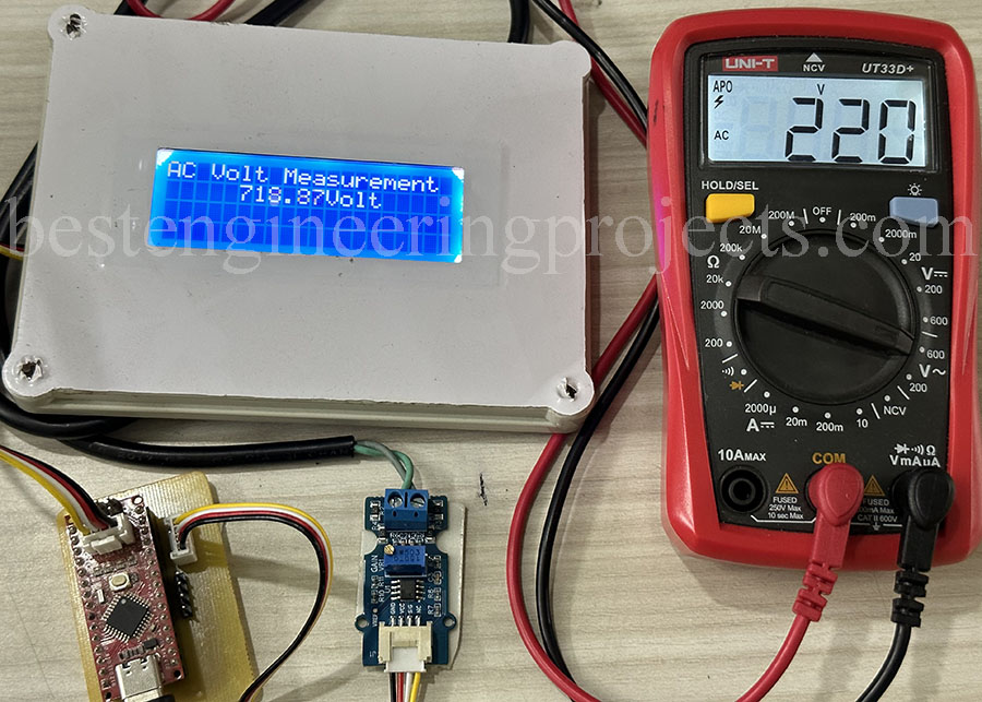
Figure 3: Setup for Calibration of Voltage Sensor
Here in my case, the reading from the multimeter is 220V while the sensor shows 718.87V, in order to get an accurate calibration value we need to do simple math.
Step 3: Suppose, x = calibration value we need to calculate than

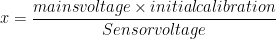

Therefore, x = 160.22
Step 4: Update the calibration value and adjust the gain if required.
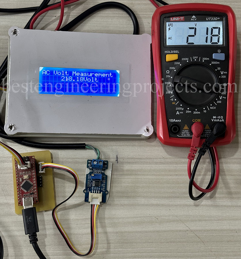
Figure 4: Author Prototype of AC Voltage Measurement using Arduino without Transformer
Software code with updated calibration value and I2C LCD
|
1 2 3 4 5 6 7 8 9 10 11 12 13 14 15 16 17 18 19 20 21 22 23 24 25 26 27 28 |
#include "MCMVoltSense.h" // Include MCM Volt Sense Library #include <LiquidCrystal_I2C.h> LiquidCrystal_I2C lcd(0x27,20,4); MCMmeter meter; // Create an instance void setup() { Serial.begin(115200); lcd.init(); lcd.backlight(); lcd.clear(); meter.VoltageStp(A0, 160.22, 1.7); // Voltage: input pin, calibration, phase_shift } void loop() { meter.analogVoltage(40,2000); // Measure the AC voltage. Arguments = (# of AC cycles, timeout) float Vrms = meter.Vrms; // Save the RMS Voltage into a variable. Serial.print("Voltage: "); Serial.print(Vrms,2); Serial.println(" V"); lcd.setCursor(0,0); lcd.print("AC Volt Measurement"); lcd.setCursor(5,1); lcd.print(Vrms,2); lcd.print(F("Volt")); delay(2000); } |
What will happen if AC voltage changes while running code will it measures changed voltage?