Many electronics enthusiasts love to design their custom control circuits. Today, we’re exploring an interesting circuit that accomplishes single relay control through multiple switches. This circuit accomplishes this achievement and introduces the utilization of EX-OR gates within control systems. Check out the article on “How to make relay switch circuit”
Before we delve into the circuit’s details, let’s first understand what an EX-OR gate is.
Exclusive OR Gate
An exclusive OR gate, often abbreviated as EX-OR performs the following logic “The output of a 2-input Exclusive OR gate assumes the 1 state if one and only one input assumes the 1 state”. The above definition is equivalent to the statement: “If A = 1, or B = 1, but not simultaneously, then Y = 1”.
Table 1: Truth table of EX-OR gate
| Input | Output | |
| A | B | Y |
| 0 | 0 | 0 |
| 0 | 1 | 1 |
| 1 | 0 | 1 |
| 1 | 1 | 0 |
Circuit Description of Multi-Switch Relay Control with EX-OR Gates
The core of our circuit revolves around a single EX-OR gate IC CD4077. The CD4077 is a CMOS IC containing four individual two-input EX-OR gates, making it a versatile component for our project.
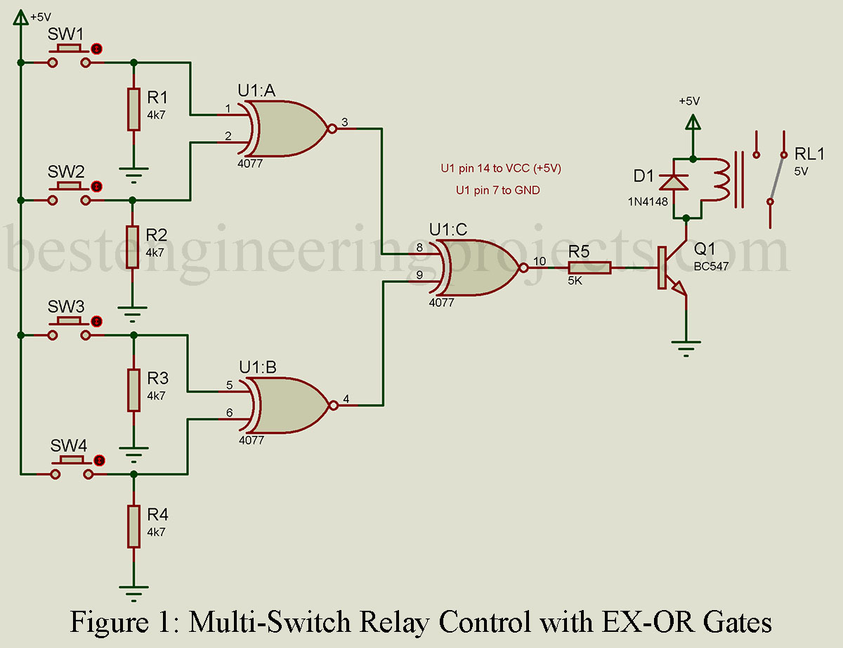
In our setup, switches SW1 and SW2 are connected to the two inputs of EX-OR gate U1:A, as illustrated in the circuit diagram. Similarly, switches SW3 and SW4 are linked to the two inputs of EX-OR gate U1:B. One input of each switch connects to +5V, while the other links into the EX-OR input. To ensure the reliability of our inputs and prevent digital debounce, we’ve incorporated pull-down resistors for each information of EX-OR gates U1:A and U1:B.
The outputs of EX-OR gates U1:A and U1:B join at the input of a third EX-OR gate, U1:C. Now, let’s explore the truth table of relay operation.
Table 2: Truth table of relay operation
| SW4 | SW3 | SW2 | SW1 | U1:A Output | U1:B Output | Relay operation |
| 0 | 0 | 0 | 0 | 0 | 0 | OFF |
| 0 | 0 | 0 | 1 | 1 | 0 | ON |
| 0 | 0 | 1 | 0 | 1 | 0 | ON |
| 0 | 0 | 1 | 1 | 0 | 0 | OFF |
| 0 | 1 | 0 | 0 | 0 | 1 | ON |
| 0 | 1 | 0 | 1 | 1 | 1 | OFF |
| 0 | 1 | 1 | 0 | 1 | 1 | OFF |
| 0 | 1 | 1 | 1 | 0 | 1 | ON |
| 1 | 0 | 0 | 0 | 0 | 1 | ON |
| 1 | 0 | 0 | 1 | 1 | 1 | OFF |
| 1 | 0 | 1 | 0 | 1 | 1 | OFF |
| 1 | 0 | 1 | 1 | 0 | 1 | ON |
| 1 | 1 | 0 | 0 | 0 | 0 | OFF |
| 1 | 1 | 0 | 1 | 1 | 0 | ON |
| 1 | 1 | 1 | 0 | 1 | 0 | ON |
| 1 | 1 | 1 | 1 | 0 | 0 | OFF |
Examining the truth table reveals that out of the 16 possible combinations of switch operations, the relay will be energized in only eight instances.
This article will take you on a journey through the fascinating world of multi-switch relay control, showcasing the pivotal role of EX-OR gates in this innovative circuit.
Component list of Multi-Switch Relay Control with EX-OR Gates
Resistors (all ¼-watt, ± 5% Carbon)
R1 – R4 = 4.7 KΩ
R5 = 15 KΩ
Semiconductors
U1 = CD4077
Q1 = BC547
D1 = 1N4148
Miscellaneous
SW1 – SW4 = Push to on/off switch
RL1 = 5V, 100 Ω SPDT relay