Are you on the hunt for a reliable mic preamp schematic to take your DIY audio projects to the next level? Look no further. In this article, we present a powerful yet straightforward mic preamplifier circuit that can transform whispers into a loud and clear conversation. Whether you’re a seasoned electronics enthusiast or a beginner, this schematic is perfect for boosting your DIY audio endeavors.
Overview of the Mic Preamp Schematic
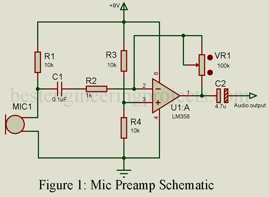
The mic preamp schematic posted here uses the capabilities of a high-gain operational amplifier, the LM385. This versatile integrated circuit, housing two amplifiers within a single package, is the key to achieving the high amplification required for your electret microphone. Despite its exceptional performance, this preamp circuit remains compact and can seamlessly fit onto a square-inch PCB (Printed Circuit Board).
Choosing the Right Microphone and Description:
For this project, we’ve chosen to work with an electret microphone. These microphones are readily available at electronics stores or can often be rescued from older appliances like headphones or telephones. An electret microphone serves as a transducer, effectively converting sound signals into electrical ones. In our schematic, we connect the microphone to the inverting terminal (pin 2) of the operational amplifier through an RC network. This network acts as a low-pass filter, permitting specific frequencies to pass while blocking others. To ensure a stable voltage reference, we employ a voltage divider network connected to the non-inverting terminal (pin 3). The amplifier then amplifies the voltage difference between these two terminals.
Customized Gain Control
To provide you with precise control over amplification, we’ve integrated a variable resistor (VR1) that links from the output (pin 1) to the inverting terminal. Simply by adjusting this potentiometer, you can finely tune the gain of the operational amplifier. Remember that excessive gain can lead to distortion, so it’s vital to find the perfect balance. If you detect distortion in the output, a simple adjustment of the potentiometer will clear it up. Our schematic also features a capacitor connected to the output of the preamp, allowing you to connect it seamlessly to an audio amplifier or even a speaker.
In conclusion, this straightforward mic preamp schematic can significantly enhance sensitivity and clarity in your audio projects. With its ease of assembly and customizable gain control, it’s an invaluable addition to any DIY audio enthusiast’s toolbox. Whether you’re pursuing a hobby or tackling larger projects, this circuit empowers you to effortlessly amplify audio signals.
Component list of mic preamp schematic
Resistors (all ¼-watt, ± 5% Carbon)
R1, R3, R4 = 10kΩ
R2 = 1kΩ
VR1 = 100kΩ
Capacitors
C1 = 0.1uF
C2 = 4.7uF
Semiconductors
IC1 = LM358
MIC1 = Electret microphone
For more electronic project ideas and helpful tips, stay tuned to our blog. Happy DIY-ing!