In a world where safety and security are a major concern, imagine having a reliable intruder alarm system that can offer peace of mind. Here is a simple intruder alarm circuit that does not need a deeper understanding of electronics.
These homemade security solutions are cost-effective also. So, if you are a DIY enthusiast or just curious about creating your own security setup. Here is a customized intruder alarm circuit that suits your needs perfectly. Let’s dive into its description and working methodology.
Circuit Description of Intruder Alarm Circuit
The circuit of intruder alarm circuit is divided into two sections i.e. transmitter circuit and the receiver circuit.
Transmitter Circuit:
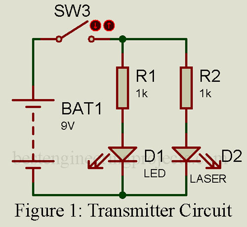
The transmitter section has a laser diode which is powered by a 9V power supply. You can use either mains operated power supply or a battery. A switch is used here to ON/OFF the transmitter circuit. An LED is also connected in parallel to a laser diode in order to indicate the power supply. The current limiting resistor is connected to both the LED and LASER diode for protection.
Receiver Circuit:
The receiving section, on the other hand, employs a Light Dependent Resistor (LDR) as the sensor, working on the principle of light resistance.

Here’s how it works:
When the laser diode emits light that falls on the LDR, it provides a base current to transistor T1, causing it to start conducting. Meanwhile, transistor T2 remains non-conductive, keeping the alarm off.
However, when someone pushes the door, the light beam incident on the LDR is interrupted, causing the LDR to offer high resistance. This change in resistance stops transistor T1 from conducting, but transistor T2 now receives a base current and starts conducting.
The output from transistor T2 is then input into AND gate N1, and this is where things get interesting. We use an IC2, which acts as a latch. When high output is received from AND gate N1, it’s connected to pins 1 and 14 of IC2.
When the output pin 12 of IC2 goes high, it’s connected to the base of transistor T3 through resistor R7. This action causes transistor T3 to start conducting, resulting in the activation of the alarm, effectively alerting you to any door movement or intrusion.
Component list of Simple Intruder Alarm Circuit
Resistors (all ¼-watt, ± 5% Carbon)
R1, R2, R6, R8 = 1 KΩ
R3 = 2.2 KΩ
R4 = 10 KΩ
R5 = 100 Ω
R7 = 2.2 KΩ
Semiconductors
IC1 (N1) = 7408
IC2 = 7473 JK flip-flop
T1 = BEL187
T2, T3 = SL100
LED1, LED2 = RED
LD1 = Laser diode
Miscellaneous
9V battery
SW1, SW2 = On/off switch
SW3 = push-to-on switch
Piezo buzzer
LDR