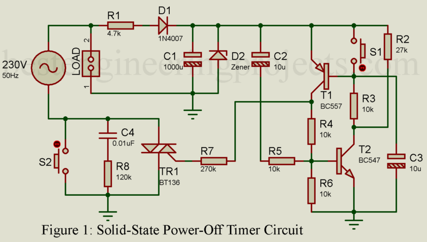
Ever left a device plugged in overnight, only to realize it’s been sipping power like a lazy vampire? We all have. Even when switched off, many devices still drink up energy, wasting precious electricity and silently adding to the bill. What if there was a smarter way? Well, guess what—there is! Today, we’re building a solid-state power-off timer circuit that not only cuts the load but consumes absolutely no energy when turned off.
Why This Circuit is a Game-Changer
You see, most circuits out there rely on relays or electromechanical switches. They work fine, but relays are noisy, slow, and they do waste energy in standby mode.
This circuit? It’s like a light switch that disappears when you don’t need it. Zero power consumption. No moving parts. All solid-state. In other words, it’s reliable, efficient, and has that modern charm engineers like us dream of.
How It Works – The Magic Behind the Curtain
Let’s simplify the magic:
- When you hit the ON switch (S2), the neutral line connects to a triac’s gate (think of the triac as a digital bouncer for your load—on or off, no in-between).
- A small rectifier circuit converts AC to DC using a diode (D1), a resistor (R1), and capacitors (C1, C2). This DC voltage powers up the transistors (T1 and T2) that work together like two buddies giving each other a high-five. Once one turns on, it keeps the other going. Symbiosis at its finest.
- The triac stays ON, and so does your load—until you hit the OFF switch (S1). Press it, and boom—the transistors stop their high-five. No gate current means the triac switches OFF, disconnecting power to the load.
- Here’s the real kicker: Once the triac is OFF, the circuit itself is starved of power. It doesn’t sip, slurp, or even sniff energy.
Circuit Components You Need
Resistors (all ¼-watt, ± 5% Carbon unless stated)
R1 = 4.7 kΩ/10W
R2 = 27 kΩ
R3, R4, R5 = 10 kΩ
R6 = 3.3 kΩ
R7 = 270 kΩ
R8 = 120 kΩ
Capacitor
C1 = 1000 µF/16V Electrolytic
C2, C3 = 10 µF/16V electrolytic
C4 = 0.01 uF / 400V
Semiconductor
D1 = 1N4007
D2 = 9.1V, 1W Zener Diode
T1 = BC557B PNP Transistor
T2 = BC547B NPN Transistor
TR1 = BT136
Miscellaneous
S1 = PUSH-TO-OFF-SWITCH
S2 = PUSH-TO-OFF-SWITCH
Step-by-Step Build Instructions
- Power Supply Setup: Connect the 230V AC input to R1 and D1. Place the Zener diode (D2) after C1 to regulate the voltage to around 9V DC.
- Triac Control Circuit:
- Link MT1 and MT2 of the triac (BT136) to the load and the neutral line. Connect its gate to T1’s collector through R7.
- Add R5 and C2 to T2’s base for the initial ON trigger.
- Transistor Pair Latch:
- Connect T1 (BC557) and T2 (BC547) in feedback mode using R3 and R4. This creates a latch that keeps the triac ON.
- Add C3 to stabilize the circuit and avoid false switching.
- ON/OFF Switches:
- Connect S2 to trigger the circuit ON.
- Link S1 to break the transistor latch and switch everything OFF.
- Testing Time: Power it up! Press S2 to turn ON your load, and press S1 to turn it OFF. Watch the magic: no standby power is consumed!
Practical Applications
This circuit is like a Swiss Army knife for power control:
- Energy-Saving Timers: Ideal for lights, fans, and appliances.
- Smart Home Automation: Use an optocoupler for external control.
- Standalone Switches: Perfect where power wastage is a concern.
It’s small, solid, and endlessly adaptable. Build it once, and it works forever.
Final Thoughts
Imagine your home filled with circuits like this—no wasted energy, no buzzing relays, no power drain. You’re not just saving on electricity bills; you’re building a smarter, more efficient world, one circuit at a time.
This power-off timer circuit is proof that sometimes, the smallest changes bring the biggest savings. Build it, test it, and see for yourself—you’ll wonder why you didn’t do it sooner. Now go grab your soldering iron and give wasted energy the boot!

Very nice on-off switch, so you tern it on with one switch and turn off with the other switch, so am I missing something? How do you set the time,
I want a timer for my workshop Iron, so I want a standard setting of 30 min, so if I don’t turn off my iron it auto turns off after 30 minutes when I leave the workshop.