An automatic lead acid battery charger circuit is designed to charge 12V, and 40Ah in different charging modes i.e. boost mode and float mode. This circuit can be used to charge large-capacity inverter batteries by replacing transformers and power transistors with higher ratings. To know the condition of the battery and charger unit, this circuit was incorporated with an audiovisual indication unit. Before going to the circuit description and working let’s see its salient features:
Features of Automatic Lead Acid Battery Charger Circuit
- Automatic charger the battery and maintain the battery charge level.
- Two-mode of charging i.e. Boost mode and Float mode
- Four state battery charge level indication
- Buzzer indicator for safe discharge
- Proper protection for the voltage regulator IC
Circuit Description of Automatic Lead Acid Battery Charger Circuit
The Automatic lead acid battery charger circuit is divided into four different sections.
Power supply for control circuit: For working of the operation amplifier we need a dual power supply i.e. positive and negative power supply. For this a center-tap transformer TR1 is used, this transformer converts 110V/220V mains supply to 12V-0-12V. This voltage is converted into a positive and negative power supply using a half-wave rectifier. The upper section of the secondary terminal (12V-0V) acts as a +ve power supply whereas the lower section (0V-12V) acts as a -ve power supply. In this section diode and capacitor are connected opposite as shown in the circuit below. This rectified output is filtered using two capacitors C1 and C2 each of 220uF.
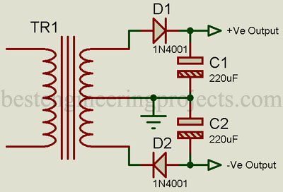
Figure 1: Power supply for control circuit
Schmitt Trigger Circuit: Schmitt trigger circuit is designed for a window of about 1V, it also avoids relay chattering. Inverting input of U1 (pin 2) is connected to the battery +ve terminal through a voltage divider network built using two series resistors R1 and R2 each of 100K. The voltage at this pin is always half of the voltage at the battery terminal. The non-inverting input of U1 (pin 3) is connected to the output of the LM7806 (U2) fixed voltage regulator through resistors R4 and R5 to get reference voltage. To protect the voltage regulator IC a diode is connected to its GND pin as shown in the figure below.
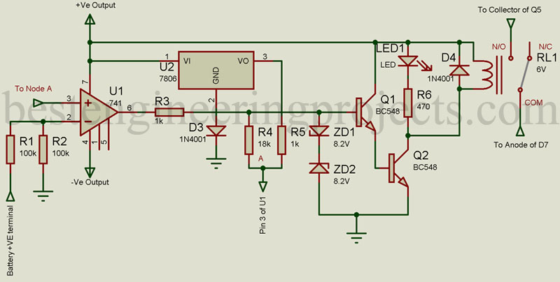
Figure 2: Schmitt Trigger Relay Driver Circuit
Two Zener diodes ZD1 and ZD2 are connected back to back to protect the transistor from overvoltage. During normal operation one of the Zener diodes becomes off thus these diodes have little or no effect. But when the output voltage from op-amp U1 exceeds its limit. One Zener turns “ON” and cuts the waveform to some level to protect the transistor.
Op-amp U1 further drives transistor Q1 which further drives transistor Q1 which further drives transistor Q2. Transistor Q2 drives the relay RL1. Glowing LED1 indicates the battery is charging in a Boost mood (high current mode).
Battery charging circuit: The battery charger unit is built around a transformer TR2, half-wave rectifier, a voltage regulator, and Darlington pair or transistor. Transformer TR2 converts 110V/220V AC mains into 18V AC which is further rectified using a half-wave rectifier. The rectified output is filtered using a high-value capacitor and is connected to the N/O contact of relay RL1.
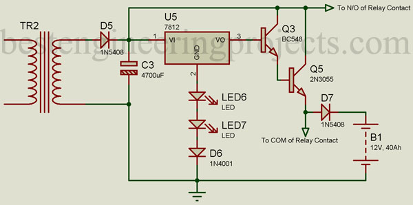
Figure 3: Battery Charging Circuit
The float charging section is built around a 12V voltage regulator, two transistors, a diode, and two LEDs. The GND pin of voltage regulator U5 (pin 2) is connected to the ground through a diode and two LEDs connected in series as shown in the figure. The GND pin is kept at 3.9V with the help of two LEDs and a diode. This is done to produce 15.9V at the output terminal (12V + 3.9V) of the voltage regulator.
This 15.9V from the output pin of U3 is connected to the base of transistor Q3, which is along with transistor Q4. These two transistors form a Darlington pair. Each transistor drops 0.7V thus, 14.5V is obtained at the emitter pin of transistor Q4. This voltage is given to the battery terminal through a series diode D7. This diode further drops 0.7V and finally, 13.8V is obtained at the battery terminal.
Battery monitoring section: Battery monitoring section is built around quad op-amp IC LM324. All the op-amp is configured as a comparator. Battery voltage is given to the non-inverting input of each comparator through a voltage divider network built using three resistors R11, R12, and R18. The output of this network is ⅓ of the battery voltage available. Inverting pin of this comparator is connected to the output of voltage regulator IC U5 through a variable resistor VR1. This is the reference voltage.
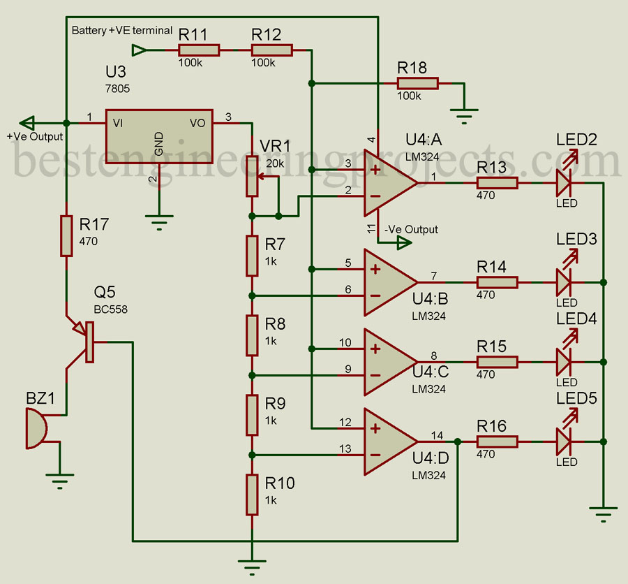
Figure 4: Battery Monitor and Indication Unit
According to the battery voltage output of the comparator charge as a result LEDs glow. Users can set the maximum and minimum charge levels by adjusting the VR1 variable resistor. When battery voltage becomes lower than 10V (i.e. lower than the safe discharge level) buzzer sounds indicate, that the safe discharge limit has been exceeded.
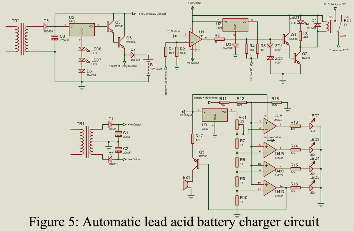
A complete circuit of the Automatic Lead Acid Battery Charger Circuit is shown in figure 5.
Working on the circuit
Battery Charging in Boost Mode: When the battery is discharged or say goes below 11.66V, the Schmitt trigger switch on the relay, and the battery starts to charge in boost mode at around 3A. When the voltage of the battery increases to 13.64V, the Schmitt trigger switches off the relay. Boost charging mode is cut off but the float charging section continuously charges the battery.
The boost charging path starts from transformer TR2, goes through diode D5, then relay N/O contact of relay RL1, and lastly diode D7.
Battery Charging in Float Mode: When the charge level of the battery reaches 13.64V, boost mode is deactivated. It continuously charges the battery and maintains the maximum battery voltage level.
The float charging path starts from transformer TR2, goes through diode D5, then through Darlington pair of transistors, and lastly through diode D7.
PCB Diagram: PCB of Automatic Lead Acid Battery Charger Circuit is designed using Altium PCB design software. The actual size solder side and component side is shown in figure 6 and 7 respectively, whereas figure 8 shows a 3D view of the charger circuit. Download the actual size PCB in PDF format from the link given below.
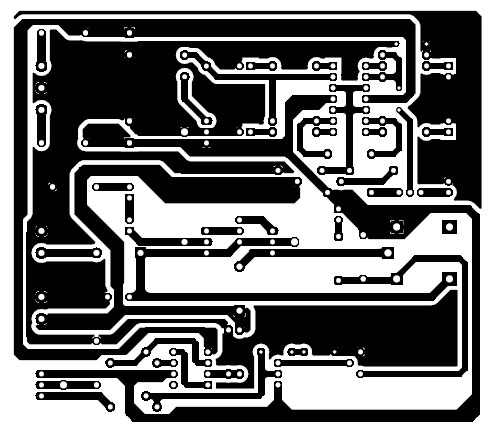
Figure 6: Solder side PCB
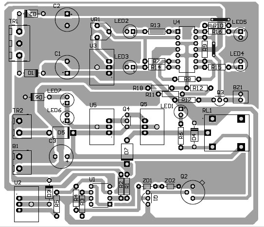
Figure 7: Component Side PCB
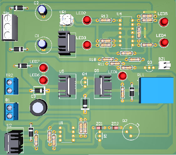
Figure 8: 3D view of automatic lead acid battery charger circuit
Download PCB design in PDF format
Component List
| Resistor (all ¼-watt, ± 5% Carbon) |
| R1, R2, R11, R12, R18 = 100KΩ
R3, R5, R7 – R10 = 1KΩ R4 = 18KΩ R6, R13 – R17 = 470Ω VR1 = 20K |
| Capacitors |
| C1, C2 = 220µF/25V
C3 = 4700µF/25V |
| Semiconductors |
| U1 = LM741
U2 = LM7806 U3 = LM7805 U4 = LM324 U5 = LM7812 Q1 – Q3 = BC548 Q4 = 2N3055 Q5 = BC558 ZD1, ZD2 = 8.2V zener diode D1 – D4, D6 = 1N4001 D5, D7 = 1N5408 LED1 – LED7 = 5mm any color LED |
| Miscellaneous |
| TR1 = 230V AC Primary to 12V-0V-12V, 500mA Secondary Transformer
TR2 = 230V AC Primary to 0V-18V, 5A Secondary Transformer RL1 = 6V, 250-ohm SPDT Relay BZ1 = Buzzer |
NICE CIRCUIT
Is this circuit able to charge 7AH battery or lower.
I will try this project