Amongst the rechargeable batteries available on the market, Lithium Iron Phosphate battery (LiFePO4 battery) or LFP battery (Lithium Ferro Phosphate) is widely used due to the various benefits offered, compared to other batteries. Longer life span, highly safe, lightweight, improved discharge, and charge efficiency are some of the advantages provided by the LiFePO4 batteries. In the market, you will find different types of LiFePO4 battery chargers that may or may not fulfill your requirements, and you may find them expensive. Previously, we had already discussed a DIY LiFePO4 battery charger circuit i.e. one can make this simple charger circuit with easily available electronics components. Now, In the article, Arduino LiFePO4 Battery Charger, you will be able to build an Arduino-based LiFePO4 battery charger with discrete electronics components.
Before designing a battery charger or charging a battery, you must know its charge and discharge rate which is given by Capacity-rating (C-rates). C-rates provide the maximum current a battery can deliver and the maximum charging rate for the batteries. For example, a 1000mAh (or 1Ah) battery rated at 1C should provide a 1A current for 1hr and can be charged with a maximum current of 1C×1Ah = 1A. Typically LiFePO4 batteries are charged between 0.3C to 1C.
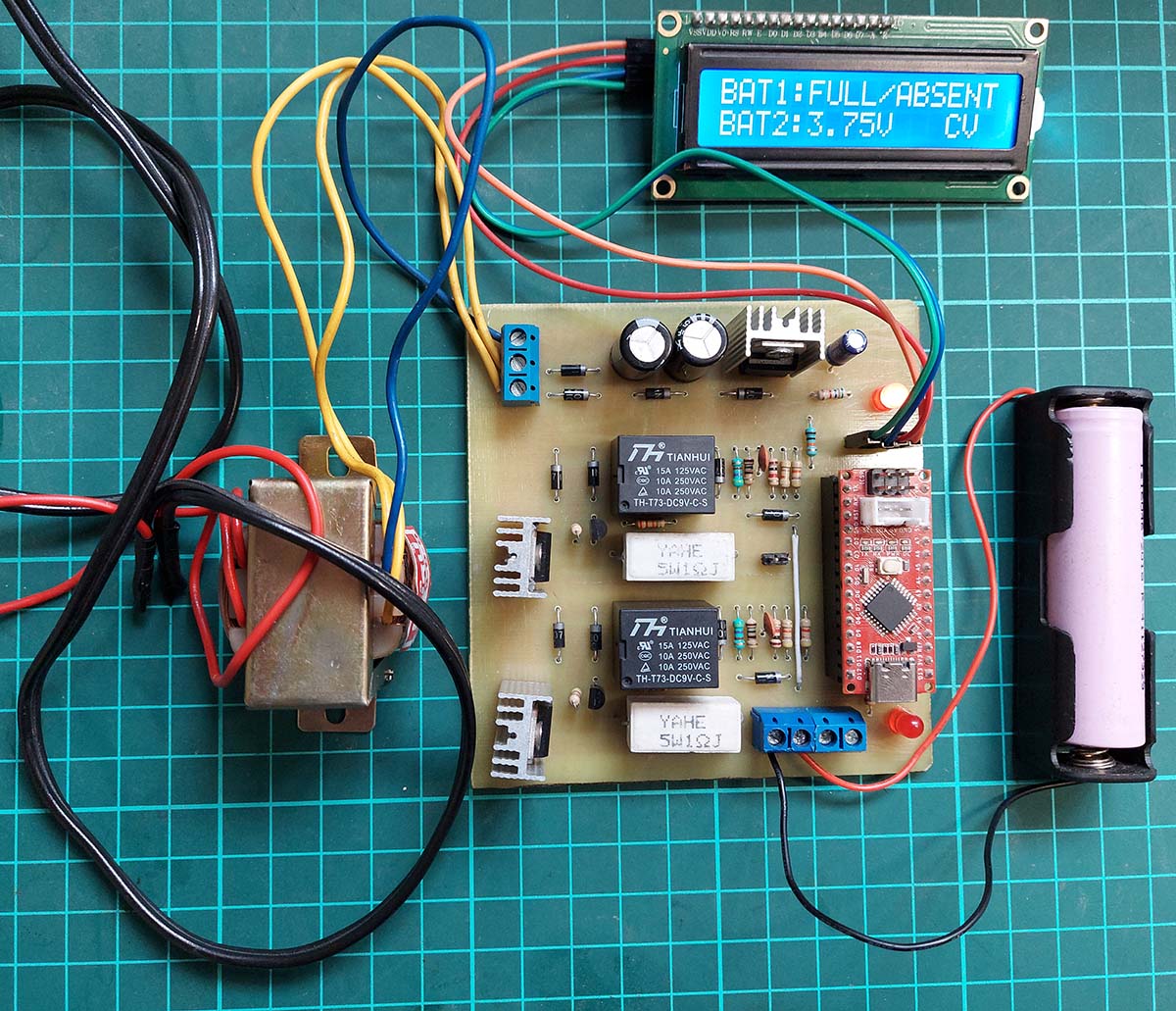 Figure: Author Prototype of Arduino LiFePO4 Battery Charger using Seeduino NANO
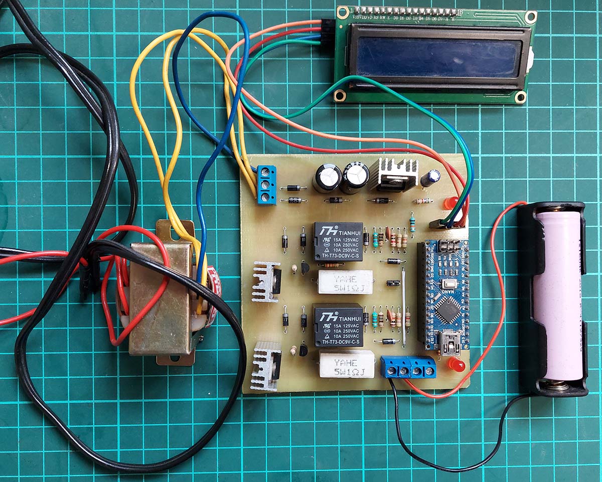 Figure: Author Prototype of Arduino LiFePO4 Battery Charger using Arduino NANO
Features of Arduino LiFePO4 Battery Charger
- Parallel charging of two 3.7V LiFePO4 batteries
- LED Indication and Display System
- Display of CC/CV modes
- Max current of 1A in CC modes
- A constant voltage of 4.2V in CV modes
Checkout the other battery charger circuit posted in bestengineeringprojects.com
- 12V Lead Acid Battery Charger Circuit
- Lithium Ion Battery Charger Circuit using LM317
- DIY LiFePO4 battery charger circuit
- Ni-Cd battery charger circuit
- 12V, 7Ah smart battery charger circuit with PCB diagram
Components Required for Arduino LiFePO4 Battery Charger
| Resistor (all ¼-watt, ± 1% Carbon Unless Stated Otherwise) |
| R1 = 10kΩ
R2, R10 = 1.2Ω at 5W (Wire wound resistor) R3, R11 = 470Ω R4, R12 = 150Ω R5, R13 = 1kΩ R6, R7, R14, R15 = 4.7kΩ R8, R16, R18 = 2.2kΩ R9, R17 = 47kΩ R19 = 5kΩ |
| Capacitors |
| C1, C2 = 0.1μF (Ceramic Capacitors)
C3 = 1000μF at 25V (Electrolytic Capacitor) C4 = 100μF at 25V (Electrolytic Capacitor) C5 = 10μF at 25V (Electrolytic Capacitor) |
| Diodes |
| D1, D2, D3, D5, D6, D7, D12 = 1N4007 (General Purpose Rectifier Diode)
D4, D8, D10, D11 = 1N5408 (General Purpose Rectifier Diode) |
| Transistors |
| Q1, Q2 = BC547 (General Purpose Switching Transistor) |
| Switching Relay |
| RL1, RL2 = 9V SPDT Relay |
| Voltage Regulators |
| U1, U2 = LM317EMP (Variable voltage regulator IC)
U3 = LM7809 (Fixed voltage regulator IC) |
| Miscellaneous |
| 16X2 Alphanumeric I2C LCD or 128×64 OLED I2C Display
Arduino UNO/NANO or Seeeduino NANO Center Tapped Step Down Transformer = 9V-0-9V, 2A LED1, LED2 = any color LED SW1 = Switch SW2 = Toggle switch CON1 = 220V AC Connector Heat Sink for Regulators |
Working Principle of Arduino LiFePO4 Battery Charger Circuit
Arduino LiFePO4 battery charger device is powered by the 220V AC supply, but to operate the Arduino board and to charge a LiFePO4 battery DC supply is required. So for the conversion of AC to DC, this device uses Center Tapped Full-Wave Rectifier. The output of the full-wave rectifier is filtered through the Low Pass Filter (LPF) and finally, the regulated supply is obtained by the use of voltage regulators. Positive 9V output from the fixed type voltage regulator LM7809 is used to power up the Arduino board, and the output of the variable voltage regulator LM317 is used for battery charging purposes.
LiFePO4 batteries are charged through the “constant current / constant voltage” (cc/cv) techniques. A LiFePO4 battery could be charged by the lead-acid or LiPo chargers but extreme cautions should be applied which is not recommended. So, the LiFePO4 battery should only be charged with a compatible charger for safety purposes and to ensure their performance and long life span. In the cc/cv technique, if the voltage of the battery is less than a certain threshold, then it is charged at constant current (cc) mode.
The battery is charged at a constant current limited by the charger until it reaches a certain threshold voltage (Battery Voltage = 3.4V). In this mode, the current remains constant, and the voltage varies and slowly increases. After a certain threshold charging voltage is reached say 3.4V, the battery is charged at constant charging voltage (cv) mode. At this mode, the voltage remains constant at the threshold and the current varies and slowly decreases until it reaches certain lower threshold values. When this condition is achieved, the LiFePO4 battery is considered to be fully charged.
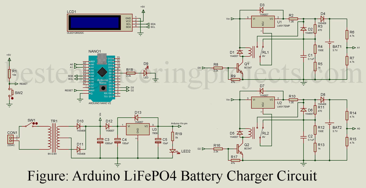
Circuits Description of Arduino LiFePO4 Battery Charger
The circuit diagram of the LiFePO4 Battery Charger is built around the Arduino Board as a controlling unit. For simplicity, the circuit diagram of the LiFePO4 Battery Charger can be divided into three parts: the power supply section, the controlling and displaying unit, and the battery charging section.
The power supply to the system is provided by the 220V AC mains supply. The 220V AC supply is connected to the primary winding of the center-tapped step-down transformer(9V-0-9V), and the secondary winding is connected to the rectifying Diodes D10 and D11. Afterward, the outputs from the diodes are filtered through the capacitor C3, and the filtered output (i.e. unregulated voltage) is provided to the 7809 fixed voltage regulator and LM317 variable voltage regulator.
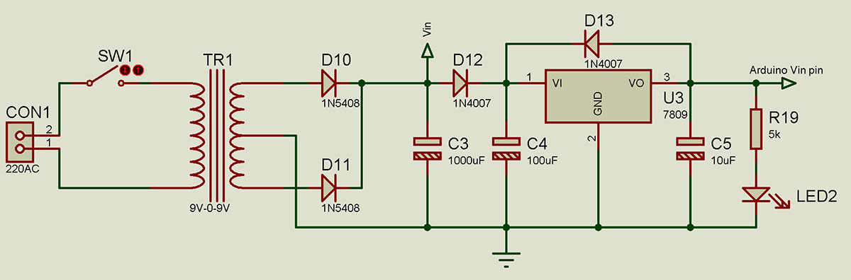 Figure: Power Supply Arrangement
The fixed voltage regulator 7809 provides an output voltage regulated at +9V which is connected to the Arduino board input voltage (Vin) pin. Diodes D12 and D13 are used for reverse current protection, and LED2 indicates that a 220V AC power supply is being applied to the system.
The battery charging section consists of two identical circuits for the charging of two 3.7V LiFePO4 batteries. The battery charging circuit is built around a variable voltage regulator LM317. From the power supply section, unregulated 9V is applied to the input voltage (Vin) pin of the LM317. The Adjustment pin of the LM317 voltage regulator is connected to the Common (COM) pin of the 9V relay. At the Normally-closed contact (NC) pin of a relay, the Constant Voltage mode circuit is connected, and at the Normally-open contact (NO) pin Constant Current mode circuit is connected.
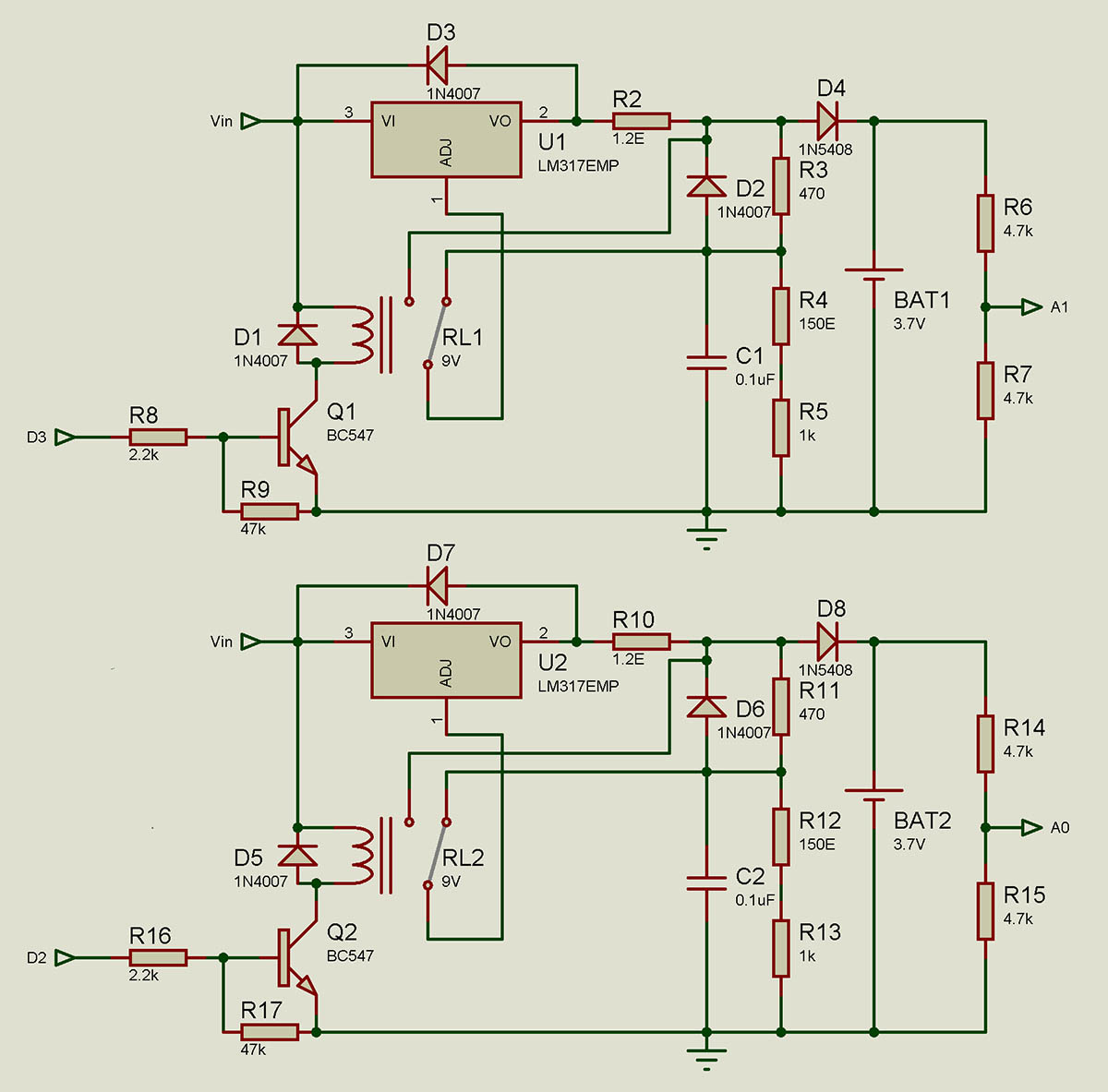 Figure: Figure: Dual LiFePO4 Battery Charger Arrangement using LM317
Energizing and De-energizing the coil of a relay, switching between constant current (cc) mode and constant voltage (cv) mode can be achieved. Terminals of the coil of a relay are connected to the transistor Q1 and the input voltage (Vin) pin of the LM317 voltage regulator. Transistor Q1 is used for fast switching of a 9V relay which is controlled by the Digital pin D3 of the Arduino board. The voltage output pin (Vout) pin of the voltage regulator LM317 is directly connected to the battery that needs to be charged ( BAT1 and BAT2 in the circuit diagram).
At constant voltage mode combination of resistors R3, R4, and R5 ensures the battery is charged at 4.2V, and in a constant current mode, the battery is charged at a constant 1A current. Diodes D1, D2, and D3 are used for the reverse current protection, and diode D4 is used as a steering diode which ensures that the battery is discharged over the voltage divider circuit. The voltage divider circuit consists of two 4.7Kohm resistors (R6 and R7) connected in parallel, and its output is connected to the analog pin A1 for the measurement of battery voltage.
When a LiFePO4 battery is placed in its holder, at first the battery is charged through constant voltage mode. Afterward, the Arduino board checks the voltage of the battery through the voltage divider circuit to decide whether to charge the battery in constant current or constant voltage mode. If the battery is to be charged at constant current mode, the relay is energized. A voltage divider circuit is used here to ensure that the voltage and current at the analog pin of the Arduino board do not exceed its maximum capacity.
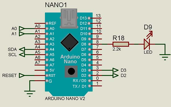 Figure: Arduino Nano Board Arrangement
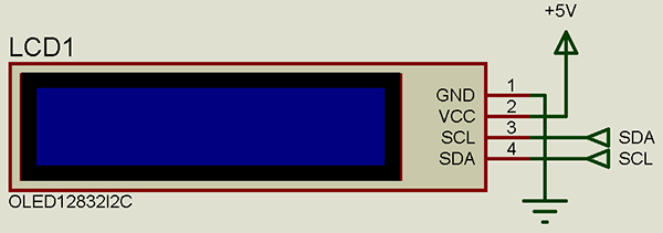 Figure: OLED I2C Display or 16×2 I2C LCD
The controlling and displaying unit consists of an Arduino for controlling and a 128×64 I2C OLED display. Arduino analog pins A0 and A1 are connected to the voltage divider circuit and A4(SDA) and A5(SCL) is connected to the SDA and SCL pins of the 128×64 I2C OLED display. Digital pins D2 and D3 of the Arduino are connected to the base pin of the transistors Q2 and Q1 respectively and a LED is connected to the digital pin D8.
Note: You can use 16×2 I2C LCD (The Code written here is for 16×2 I2C LCD)
A 128×64 I2C OLED display is used to monitor whether the battery is charging at constant current (cc) or constant voltage (cv) and to check the voltage of the battery. An LED connected to the D8 pin of Arduino indicates whether the battery is charging or fully charged. While charging, the LED continuously blinks at regular intervals, and when fully charged, it stops blinking.
Before charging a LiFePO4 battery, the battery mustn’t be physically damaged, and polarity should be maintained while putting on the battery holder.
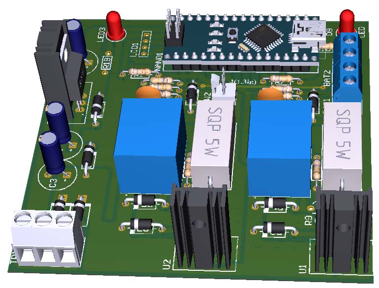
PCB Design:
PCB Design of Arduino LiFePo4 Battery charger is designed using Altium Design Software. Solder side PCB, Component side PCB, and 3D design are shown in the picture below. You can download the PCB in PDF format from the link given below.
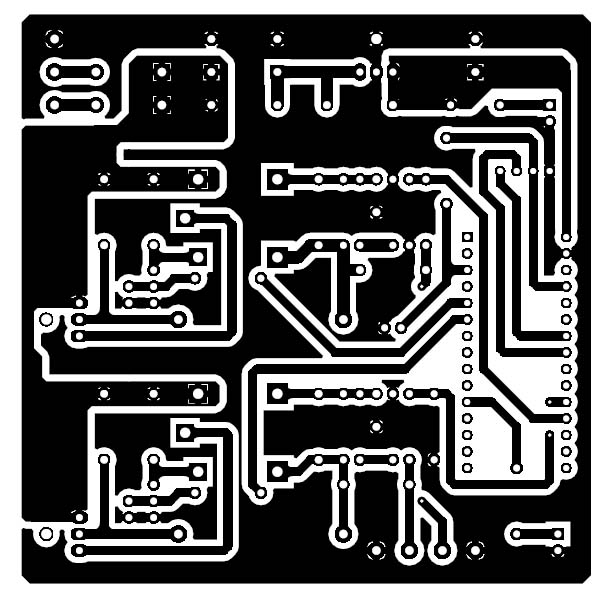 Figure: Solder Side PCB
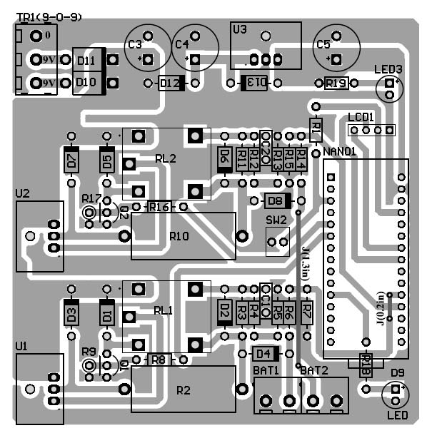 Figure: Component Side PCB
Click here to download PCB Diagram
Software Code: Software code is written in C/C++ and is compiled using Arduino IDE. The Software basically checks the battery voltage and switches between CC and CV.
|
1 2 3 4 5 6 7 8 9 10 11 12 13 14 15 16 17 18 19 20 21 22 23 24 25 26 27 28 29 30 31 32 33 34 35 36 37 38 39 40 41 42 43 44 45 46 47 48 49 50 51 52 53 54 55 56 57 58 59 60 61 62 63 64 65 66 67 68 69 70 71 72 73 74 75 76 77 78 79 80 81 82 83 84 85 86 87 88 89 90 91 92 93 94 95 96 97 98 99 100 101 102 103 104 105 106 107 108 109 110 111 112 113 114 115 116 117 118 119 120 121 122 123 124 125 126 127 128 129 130 131 132 133 134 135 136 |
#include <LiquidCrystal_I2C.h> //Library for I2C lcd LiquidCrystal_I2C lcd(0x27,20,4); #define ON 1 #define OFF 0 #define CC_MODE 1 #define CV_MODE 0 #define OUTPUT_RELAY1 2 #define OUTPUT_RELAY2 3 #define Blinker 8 float EMF_BAT1 = 0; float EMF_BAT2 = 0; int EMF_MIN = 350; int EMF_MAX = 360; int Relay1status = CV_MODE; int Relay2status = CV_MODE; char TEMP_STR[10]; void setBlinker ( int status ) { if (status) //== on digitalWrite(Blinker,HIGH); else // off digitalWrite(Blinker,LOW); } void setRelay1 ( int status ) { Relay1status = status; if (status) //== on digitalWrite(OUTPUT_RELAY1,HIGH); else // off digitalWrite(OUTPUT_RELAY1,LOW); } //=============================================================== void setRelay2 ( int status ) { Relay2status = status; if (status) //== on digitalWrite(OUTPUT_RELAY2,HIGH); else // off digitalWrite(OUTPUT_RELAY2,LOW); } void setup() { Serial.begin(9600); lcd.init(); //initialization the lcd lcd.backlight(); pinMode(OUTPUT_RELAY1, OUTPUT); pinMode(OUTPUT_RELAY2, OUTPUT); lcd.setCursor(0,0); lcd.print("LiFePO4 Charger"); delay(2000); lcd.clear(); } void loop() { setBlinker(OFF); delay(100); setBlinker(ON); delay(100); int Value1 = analogRead(A0); int Value2 = analogRead(A1); EMF_BAT1 = Value1 * ((10.0)/1023.0); EMF_BAT2 = Value2 * ((10.0)/1023.0); Serial.println(EMF_BAT1); Serial.println(EMF_BAT2); lcd.setCursor(0,0); lcd.print("BAT1:"); if(Relay1status == CC_MODE && Value1>600) { lcd.print(F("FULL/ABSENT")); setRelay1(CV_MODE); } else if(Relay1status == CV_MODE && Value1>=430) { lcd.print(F("FULL/ABSENT")); setRelay1(CV_MODE); } else if(Value1<250) { lcd.print(EMF_BAT1); lcd.print (F("DEAD/ERR ")); setRelay1(CV_MODE); } else if(Value1>345) { lcd.print(EMF_BAT1); lcd.print (F("V CV ")); setRelay1(CV_MODE); } else if(Value1<=345) { lcd.print(EMF_BAT1); lcd.print (F("V CC ")); setRelay1(CC_MODE); } lcd.setCursor(0,1); lcd.print("BAT2:"); if(Relay2status == CC_MODE && Value2>600) { lcd.print(F("FULL/ABSENT")); setRelay2(CV_MODE); } else if(Relay2status == CV_MODE && Value2>=430) { lcd.print(F("FULL/ABSENT")); setRelay2(CV_MODE); } else if(Value2<250) { lcd.print(EMF_BAT2); lcd.print (F("DEAD/ERR ")); setRelay2(CV_MODE); } else if(Value2>345) { lcd.print(EMF_BAT2); lcd.print (F("V CV ")); setRelay2(CV_MODE); } else if(Value2<=345) { lcd.print(EMF_BAT2); lcd.print (F("V CC ")); setRelay2(CC_MODE); } } |
Nice Post