Arduino is an open-source that is designed for artists or for those who do not have an electronic background. Here, in this article, we are going to show you the method of making a battery charger circuit controlled using an Arduino uno board. The project Arduino Controlled 12V battery charger circuit is an advanced version of the previous posted project “12V, 7Ah Smart Battery Charger with PCB Diagram”. This charger also has the features of bulk stage charging and float stage charging as in the previous circuit.
Silent features of Arduino Controlled 12V battery charger circuit
- Charge the battery in different stages i.e. bulk stage charging and float stage charging.
- 16×2 LCD for better visual indication of charging status of the battery and fully charged.
- The simple circuit is thus understandable to everyone.
- Automatic charging voltage and current according to the battery status.
- The high output current of about 5 Amp. Max.

Components Required for Arduino Controlled 12V battery charger circuit
| Resistor (all ¼-watt, ± 5% Carbon Unless Stated Otherwise) Ω µF |
| R1 = 0.2 Ω/ 5W (Wire wound)
R2 = 1.5 KΩ R3 = 470 Ω R4, R13 = 1 KΩ R5, R7, R9, R11 = 3.3KΩ R6 = 330 Ω R8 = 4.7 KΩ R10 = 2.2 KΩ R12 = 22 KΩ VR1 = 2 KΩ POT. VR2 = 10 KΩ POT. |
| Capacitors |
| C1, C2, C4 = 10 µF, 35V or 63V (Electrolytic Capacitor)
C3 = 2000 µF, 35V or 63V (Electrolytic Capacitor) C5 = 100 µF, 24V (Electrolytic Capacitor) |
| Semiconductors |
| IC1 = LM338
IC2 = LM7812 T1, T2 = BC547 D1, D2, D7 = 1N5408 D3, D4. D6, D8 = 1N4007 Arduino UNO Board |
| Miscellaneous |
| LCD1 = 16×2 Alphanumeric LCD
SW1 = Push-to-on Switch Jumpers for connectors LED1 = 5mm any color LED Heat Sink for IC1 and IC2 X1 = 220V AC Primary to 15V-0-15V, 3A Secondary Transformer |
Circuit Description of Arduino Controlled 12V battery charger circuit
The circuit is shown in figure 1 and made using Proteous. For circuit description and working of Arduino Controlled 12V battery charger circuit we are dividing the entire section into 4 parts.

Voltage Stepdown and Rectifier Unit | Arduino Controlled 12V battery charger circuit
The stepdown and rectifier is built around 220V AC primary to the 15V-0-15V secondary transformer, two high-power rectifier diode, and a filter capacitor (C3 = 2000 µF). This arrangement is a full-wave rectifier with a filter circuit. Transformer X1 step down the AC input voltage to 30V AC which is rectified using two diodes D1 and D1 and filtered using capacitor C3. This DC output contains ripple and the magnitude of DC volt is about 28.5V (30V-0.7V-0.7V = 28.5V). Approximate 1.5V is the voltage drop across diode D1 and D2 combined.
Battery Charger Circuit | Arduino Controlled 12V battery charger circuit
The charger circuit is designed around an adjustable voltage regulator IC (LM338). Filtered DC voltage is given to the input pin of IC1 (LM338). This IC can provide a regulated voltage of about 1.2V to 32V at excess of 5A current. Diode D3 and D4 are protection diodes and hence protect from reverse polarity voltage sources.
Transistor T1 and T2 control the voltage at output i.e. when the battery is fully charged then output is set to float charging state and when the battery is in charging state the then the output is set to bulk charging.
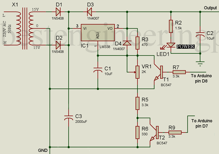 Figure 2: Adjustable Voltage Regulator with Rectifier
Working of the adjustable voltage regulator
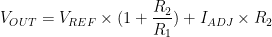
The output voltage (V0ut) of the adjustable voltage regulator is described by the following equation
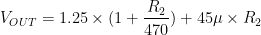
Where R2 = VR1 + R5 + R6 i.e. combination of these three resistors.
R1 = 470-ohm
VREF = 1.25V
IADJ = 45 uA
Therefore the above equation can be re-written as:
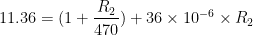
Mathematical Calculation of theoretical value of R2
The maximum voltage at which we can charge the 12V battery is about 14.2V. So, let us assume VOUT = 14.2V and calculate the value of variable resistance VR1.


Therefore,

Now, Calculate the value of variable resistor VR1


Therefore, theoretical value of variable resistor VR1 is

So, adjust the wiper of the variable resistor in between.
Now let’s see the working of the automatic charger stage in three different cases.
CASE 1: When Both the transistor is OFF i.e. both the digital pin D8 and D9 of the Arduino board is low.

Value of resistor R2 is a combination of all three resistor VR1, R5, and R6 because this two transistor is off and does not conduct any voltage i.e. R2 = 4788-ohm
So, the voltage output can be calculated as

Therefore

Thus, battery Charge at bulk stage
CASE 2: When the Transistor T1 (Charger OFF Transistor) is off and transistor T2 (charge low transistor) is ON. In this case resistor, R6 does not contribute any resistance to adjustable resistance because conducting transistor T2 heavily conducts and passes all the voltage to the ground from the endpoint of R5. Thus, equivalent resistance (R2) = 4788 – 330 = 4458-ohm.


Therefore, output voltage VOUT


Thus, in this case, the charger circuit maintains only a float charging state i.e. battery charger supply 13.2 voltage to the battery at a constant rate. As we all know that batteries have some internal resistance and start to self-discharge at a constant rate and to solve this issue we used here float charging concept.
CASE 3: When both the transistor is on, in this case, no resistor (i.e. VR1, R5, and R6) contributes in R2 i.e. R2 becomes zero because transistor T2 starts to conduct and all the voltage is passed from collector to emitter to ground. So, the output voltage can be calculated as


Fixed Voltage Regulator | Arduino Controlled 12V battery charger circuit
Fix voltage regulator 7812 (IC2) is used to power the Arduino uno board and also used to calculate the power consumption to find whether the battery is good or not. Two diodes D5 and D6 are used for protection as in the above circuit. A voltage divider network is made using two resistors R8 and R10 which are used to measure the voltage difference. One output between these two resistors is given to analog pin A1 of Arduino uno board as shown in the circuit diagram.
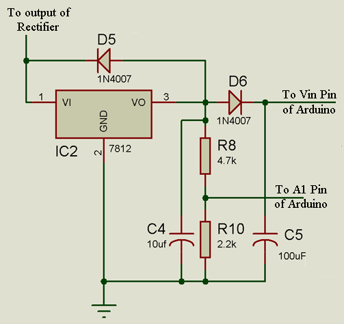 Figure 3: Fixed Voltage Regulator Circuit
Display Unit | Arduino Controlled 12V battery charger circuit
The display unit is built around a 16×2 alphanumeric LCD and Arduino board. As this LCD is based on Hitachi so for contrast we don’t need a variable resistor. A fixed value resistor is connected to the VDD pin (pin 3) of LCD to the ground as shown in the circuit diagram. The higher data pin of LCD (D4, D5, D6, and D7) is connected to Arduino uno digital pin (D5, D4, D3, and D2) respectively. Where enable (E) and Reset/Set (RS) pin of LCD is connected to D6 and D7 respectively as shown in the circuit diagram. LED+ and LED- (pin 15 and pin 16) of LCD is connected to +Vcc (5V of Arduino) through current limiting resistor R13 and GND respectively. If you are new to Arduino and LCD interfacing then please watch this video before interfacing: Interfacing of 16×2 LCD to Arduino UNO Board.
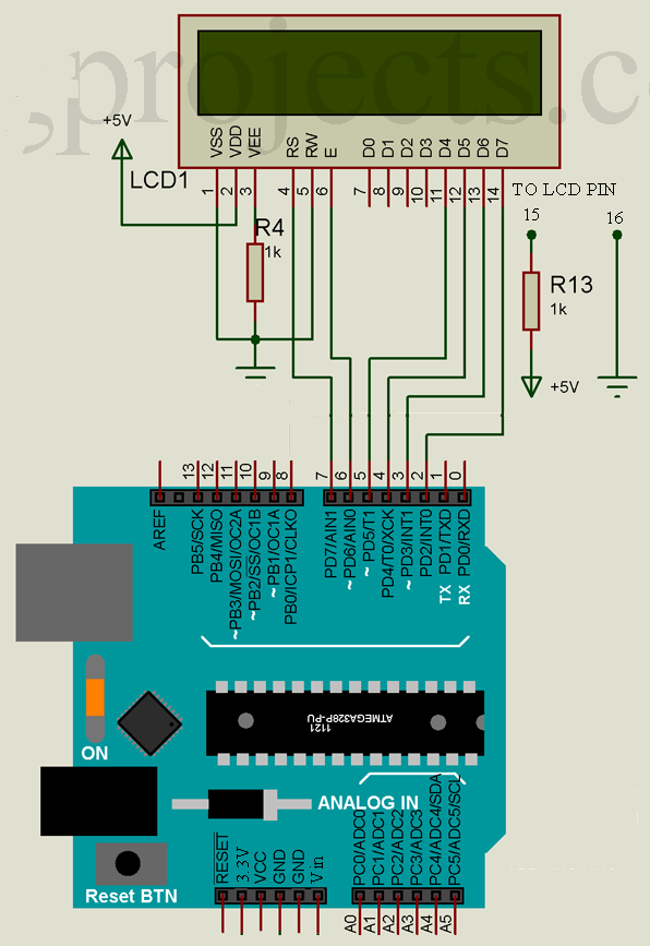 Figure 4: Display Unit for Arduino Battery Charger
Battery Status | Arduino Controlled 12V battery charger circuit
For checking battery status press the switch SW1 for a few moments. Arduino board gets power from the battery and it measures the voltage from the voltage divider network formed using resistor R12 and variable resistor VR2. The jumper is used for calibration of the circuit for battery testing.
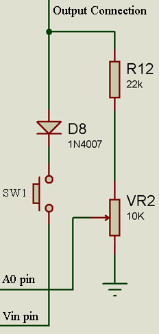 Figure 5: Battery Status Circuit
Software Code | Arduino Controlled 12V battery charger circuit
The software code for Arduino controlled 12V battery charger circuit is written in Arduino programming language and compiled using Arduino IDE.
|
1 2 3 4 5 6 7 8 9 10 11 12 13 14 15 16 17 18 19 20 21 22 23 24 25 26 27 28 29 30 31 32 33 34 35 36 37 38 39 40 41 42 43 44 45 46 47 48 49 50 51 52 53 54 55 56 57 58 59 60 61 62 63 64 65 66 67 68 69 70 71 72 73 74 75 76 77 78 79 80 81 82 83 84 85 86 87 88 89 90 91 92 93 94 95 96 97 98 99 100 101 102 103 104 105 106 107 108 109 110 111 112 113 114 115 116 117 118 119 120 121 122 123 124 125 126 127 128 129 130 131 132 133 134 135 136 137 138 139 140 141 142 143 144 145 146 147 148 149 |
#include <LiquidCrystal.h> // RS E D4 D5 D6 D7 LiquidCrystal lcd(7, 6, 5, 4, 3, 2); int ADC_PIN = A0; int PWR_PIN = A1; int CHRG_OFF_PIN = 8; int CHRG_LOW_PIN = 9; int CALIBRATION_PIN = 10; int LED_IND = 13; int ADC_VAL = 0; int PWR_VAL = 0; int VOLTS = 0; int isCalibrate=0; int loopno=0; void setup() { pinMode(LED_IND, OUTPUT); pinMode(CHRG_OFF_PIN, OUTPUT); pinMode(CHRG_LOW_PIN, OUTPUT); pinMode(CALIBRATION_PIN, INPUT); digitalWrite(CHRG_OFF_PIN, HIGH); digitalWrite(CHRG_LOW_PIN, HIGH); delay(2000); lcd.begin(16, 2); lcd.setCursor(0, 0); lcd.print ("Arduino controld" ); lcd.setCursor(0, 1); lcd.print("12V battery chrgr"); delay(1000); lcd.clear(); } void loop() { START: loopno++; isCalibrate = digitalRead ( CALIBRATION_PIN ); digitalWrite(LED_IND, HIGH); if ( isCalibrate == HIGH ) { digitalWrite(CHRG_OFF_PIN, LOW); digitalWrite(CHRG_LOW_PIN, LOW); } else { digitalWrite(CHRG_OFF_PIN, HIGH); digitalWrite(CHRG_LOW_PIN, HIGH); } delay(20); PWR_VAL = analogRead (PWR_PIN); delay(20); ADC_VAL = analogRead(ADC_PIN); VOLTS = (ADC_VAL+2) / 4; lcd.setCursor(0, 0); lcd.print (VOLTS/10); lcd.print ("."); lcd.print (VOLTS%10); lcd.print (" V "); if ( isCalibrate == HIGH ) { lcd.setCursor(0, 1); //lcd.print ("STATUS:" ); lcd.print ("CALIBRATION....."); lcd.setCursor(7, 0); lcd.print ("A0 = " ); lcd.print (ADC_VAL); lcd.print ( " " ); delay(500); goto START; } if ( VOLTS>130 ) { digitalWrite(CHRG_OFF_PIN, LOW); digitalWrite(CHRG_LOW_PIN, HIGH); lcd.setCursor(7, 0); lcd.print ("CHRG.FULL" ); lcd.setCursor(0,1); if(PWR_VAL<600) lcd.print( " CHARGER IS OFF " ); else lcd.print ("FLOAT CHARGING. " ); } else if ( VOLTS<=15 ) { digitalWrite(CHRG_OFF_PIN, HIGH); digitalWrite(CHRG_LOW_PIN, HIGH); lcd.setCursor(7, 0); lcd.print ("NO BATTRY" ); lcd.setCursor(0,1); if(PWR_VAL<600) lcd.print( " CHARGER IS OFF " ); else lcd.print (" NOT CHARGING. " ); } else if ( VOLTS<80 ) { lcd.setCursor(7, 0); lcd.print ("BATT:DEAD" ); lcd.setCursor(0,1); if(PWR_VAL<600) lcd.print( " CHARGER IS OFF " ); else lcd.print (" SLOW CHARGING. " ); delay(1000); digitalWrite(CHRG_OFF_PIN, LOW); digitalWrite(CHRG_LOW_PIN, HIGH); } else if ( VOLTS<110 ) { digitalWrite(CHRG_OFF_PIN, LOW); digitalWrite(CHRG_LOW_PIN, LOW); lcd.setCursor(7, 0); lcd.print ("BATT:WEAK" ); lcd.setCursor(0,1); if(PWR_VAL<600) lcd.print( " CHARGER IS OFF " ); else lcd.print (" FAST CHARGING. " ); } else { digitalWrite(CHRG_OFF_PIN, LOW); digitalWrite(CHRG_LOW_PIN, LOW); lcd.setCursor(7, 0); lcd.print ("BATT:GOOD" ); lcd.setCursor(0,1); if(PWR_VAL<600) lcd.print( " CHARGER IS OFF " ); else lcd.print (" FAST CHARGING. " ); } if ( loopno%2 ) { lcd.setCursor(15,1); lcd.print ( '.' ); } if(loopno>1000) loopno = 0; digitalWrite(LED_IND, LOW); delay(2000); } |
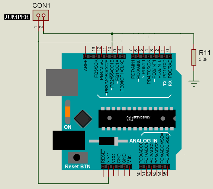 Figure 6: Calibration Circuit
Calibration of Arduino Controlled 12V Battery Charger Circuit
- Connect all the circuit components as shown in the circuit diagram.
- Upload the code to the Arduino Uno board.
- Short the jumper (CON1).
- Connect the multimeter in place of the battery, and set the multimeter in DC voltage measurement mode. (V probe of the multimeter is connected to the output of diode D7 and COM probe to GND of the circuit).
- Adjust the wiper of VR1 until the multimeter shows 14.2V reading. If the multimeter reads 14.2V fix the wiper of VR1.
- Adjust the VR2 until LCD 14.2V and fix the wiper of VR2.
- Now, remove the jumper and multimeter and connect the battery. Your device Arduino-controlled 12V battery charger is ready to use.
Hello, I want to use a solar panel instead how can I work on it?
I used a solar panel in place of the panel but the display doesn’t work it just charges the battery. How can I get it to display