Common Emitter Configuration of PNP Transistor

typical output characteristic of a pnp ce ge transistor

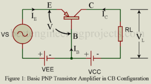
In the common-emitter configuration of PNP, the transistor emitter is the terminal common to both the input side and output side. The signal to be amplified is applied between base and emitter forming the input circuit while the amplified output voltage is developed across load impedance in the collector-to-emitter forming the output circuit. Figure 1 gives the basic circuit of a CE amplifier using load resistor RC. The Large Signal Current Gain | Common Emitter Configuration of PNP Transistor In a CB transistor, IE forms the input current while IC is…

Read More

Input and Output Characteristic Curves of CB Transistor

currents and voltages in a pnp CB transistor biased in the active region

Here in this article we will going to discuss about characteristic curves of CB transistor like static input and static output characteristic curve of CB transistor (Common Base). Characteristic Curves of Transistor in Common Base Configuration Figure 1 shows a PNP transistor connected in Common Base (CB) configuration. Base is the terminal common to the input side and the output side and this terminal has been grounded. Then we are left with two voltage variables namely VEB and VCB. Further the current IB is ignored since it is nothing but…

Read More

Amplifying Action of Transistor

amplifier action of transistor

In this article you will learn about emitter efficiency, base transport factor, The early effect, dynamic emitter resistance and amplifier action of transistor. What do you mean by amplifying action of transistor? A transistor may serve various functions but basically it is used to amplify an electrical signal. Figure 1 gives the basic circuit of a PNP transistor amplifier in common base (CB) configuration. However, we may use an NPN transistor and get the same results. In figure 1, the transistor is biased for active region operation i.e. JE is…

Read More

Current Components in a Transistor in Active Region Operation

current components in a pnp transistor with JE forward biased and jc reverse biased

Figure 1 shows the various current components in a pnp transistor operating in the active region. The entire emitter current IE consist of two parts (i) hole current IpE carried by holes diffusing across JE from p-type emitter to n-type base and (ii) electron current InE carried by electrons diffusion across JE from n-type base to p-type emitter. The ratio equals where and are respectively the conductivity of the p-type emitter region and n-type base region. Typically > . Hence in a pnp transistor, IpE>>Inr and hence we may neglect…

Read More

Types of Transistor on the Method of Construction

epitaxial planar transistor

A bipolar junction transistor (BJT) forms an extension of a PN diode. It is three-layer semiconductor device with two junctions. Further it is a bipolar device i.e. the current is carried by two types of charge carriers namely electrons and holes and hence the device is called a Bipolar Junction Transistors. A BJT is basically used as an amplifier i.e. as a circuit for amplifying or increasing the magnitude of a periodic or an a-periodic voltage or current. A junction transistor may be of PNP type or NPN type and…

Read More

Class B Push Pull Amplifier

class b push pull amplifier waveform

In class B push pull amplifier, output current (collector current) flows for only half the cycle of the input signal. Hence distortion is excessive. Single ended operation is, therefore, not possible in class B audio amplifier. Class B audio (un-tuned) amplifier must necessarily use push pull operation to reduce distortion. In effect, in class B push pull amplifier, one transistor say Q1 conduct during one half cycle while the other transistor namely Q2 conducts during the other half cycle. Class A power amplifiers may use either single ended or push…

Read More

Pushpull Amplifier | Merits of Pushpull Operation

pushpull amplifier using two transistors

In a power amplifier using only one transistor, referred to as single ended amplifier, in spite of all care in design and operation, appreciable distortion results due to non-linearity of transfer characteristics. Such a distortion may be greatly reduced by using pushpull operation employing two transistors in a single stage as shown in figure 1. In the pushpull amplifier, the input signal is applied to the input of the two transistors through a centre tapped transformer TR1. Then the voltages V1 and V2 across the two halves of the center…

Read More

Negative Feedback Amplifier Circuit | Merits

two stage rc coupled amplifier with voltage series negative feedback

Negative feedback, no doubt, reduces the gain of an amplifier. Despite this drawback, negative feedback is popularly used in amplifiers because of its various merits discussed below. Stability of Gain Negative feedback results in increased stability of gain of the amplifier despite variations in the values of circuit components and device (BJT and FET) parameters caused due to such factors as temperature change, aging, replacement of circuit components, and supply voltage variation. Consider the feedback equation: Usually we keep . Then the feedback equation reduces to the following form:          …

Read More

Feedback in Amplifiers | Feedback Techniques

block diagram of feedback amplifier

What is Feedback? What is Feedback in Amplifier? Feedback: Feedback is a phenomenon of universal importance and has, therefore, entered the general vocabulary. Thus, consider the following situation: you are an officer. You have instructed a subordinate to do a certain job. After some time, the person informs you about the state of job, whether satisfactorily completed or there are some difficulties. Thus, information constitutes the feedback. You definitely want this feedback to ensure that the job was been done; if not then what corrective measures are to be adopted.…

Read More

Maximum Collector Efficiency of Class A Amplifier

ac load line for ideal distortionless amplification

Maximum Collector Circuit Efficiency of Class A Amplifier Conversion Efficiency An amplifier draws a.c. power from dc supply (collector supply VCC in CE amplifier) and converts a part of it into useful a.c. power delivered to the load impedance. The ratio of the a.c. output power to the d.c. power from the supply source in the output is called the conversion efficiency, also called collector circuit efficiency in the case of CE amplifier and is denoted by Greek letter . Thus,           ……(1) For present analysis, we assume a resistance…

Read More