Negative feedback, no doubt, reduces the gain of an amplifier. Despite this drawback, negative feedback is popularly used in amplifiers because of its various merits discussed below.
-
Stability of Gain
Negative feedback results in increased stability of gain of the amplifier despite variations in the values of circuit components and device (BJT and FET) parameters caused due to such factors as temperature change, aging, replacement of circuit components, and supply voltage variation.
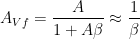
Consider the feedback equation: 
Usually we keep  . Then the feedback equation reduces to the following form:
 …..(1)
From equation 1 we see that the gain now depends only on the feedback factor  . Hence by using only stable passive elements in the feedback network, high stability of gain may be obtained.
-
Reduction in Frequency and phase Shift distortion
Equation (1) shows that on using huge negative feedback and on using a feedback network containing only resistive elements, the overall gain becomes independent of frequency. Hence frequency and phase shift distortion become negligible.
-
Reduction in Nonlinear Distortion
When a large amplitude signal is applied to a stage of a multistage amplifier, the operation of the amplifier device goes beyond its range of linear operation and results in harmonic i.e. generation of harmonic frequency terms. Next, we use negative feedback and increase the input signal by the same factor by which the gain is reduced. Thus, the output signal magnitude remains unaltered. However, this results in a reduction in harmonic distortion. It may be proved as below.
Let the input signal be sinusoidal and let only the second harmonic term of value B2 be generated within the amplifier. Let this second harmonic term become B2f in the presence of negative feedback. This B2f results in the term  at the input of the basic amplifier and a term
  in the output. Thus, the output contains two terms: (i) B2 generated within the basic amplifier and (ii) representing the feedback component.
Thus, 
Or,  …….(2)
Both quantities A and are generally functions of frequency and must, therefore, be evaluated at the second harmonic frequency.
From Equation (2) it is evident that their results reduction in harmonic distortion.
-
Reduction in Noise
We have seen that negative feedback reduces the nonlinear distortion generated within the amplifier by a factor  . By the same reasoning, the noise introduced within the amplifier also gets reduced by the factor on using negative feedback,
-
Modification of Input and Output Impedances
It may be established that:
(a) Voltage sampling decreases the output impedance
(b) Current sampling increases the output impedance
(c) Series mixing increases the input impedance
(d) Shunt mixing decreases the input impedance
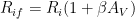
Voltage sampling alone with series mixing is most popularly used. In a voltage amplifier using voltage-series feedback, the effective input impedance gets increased by the factor 
Thus  ……(3)
……(3)
Similarly using voltage sampling, the output impedance in feedback amplifier gets reduced by the factor  . Thus,
 …..(4)
Negative Feedback Amplifier Circuits
Depending on the method of sampling namely voltage sampling or current sampling and on the method of mixing namely series mixing or shunt mixing, we may classify feedback amplifiers into the following four categories:
- Feedback amplifiers using voltage-series feedback
- Feedback amplifiers using voltage-shunt feedback
- Feedback amplifiers using current-series feedback
- Feedback amplifiers using current-shunt feedback
Out of these four types, the voltage-series feedback amplifiers are most popularly used. A brief description of a few typical feedback amplifiers is taken up here.
Typical Amplifiers using voltage Series feedback
Here we consider the following amplifier circuits using voltage-series negative feedback:
- Emitter follower
- FET source follower
- Two-stage voltage-series feedback amplifier
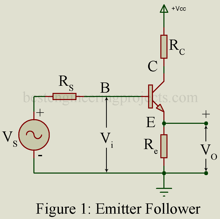
Emitter Follower
Figure 1 gives the circuit using load resistor Re in the emitter circuit. An additional resistor Rc is usually placed in the collector circuit for protection. Output voltage Vo is developed across the emitter circuit resistor Re. this entire output voltage Vo is sampled and it constitutes the feedback signal Vf. Further this feedback signal Vf comes in series opposition with the input signal Vs. hence this forms a case of negative voltage series.
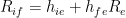
Results of Analysis: Analysis yields the following results:
 …..(5)
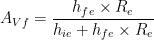 …..(5)
If  .
.
- …….(6)
- ……(7)
 …….(6)
 ……(7)
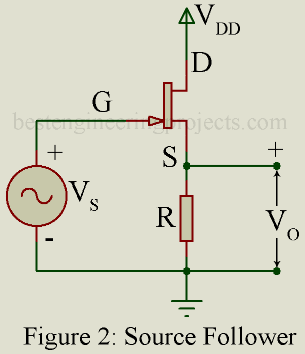
……(7)FET Source Follower
Figure 2 gives the basic circuit without biasing circuit. The output voltage Vo across R forms the sampled signal. The feedback signal is the voltage Vf across R and it comes in series opposition with the input signal Vs. Hence this circuit forms a case of voltage-series negative feedback.
Results of Analysis: Analysis yields the following results:
- …….(8)
 …….(8)
If 
- …….(9)
 …….(9)
But 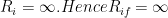
- …….(10)
 …….(10)
Two-stage Voltage-series Feedback Amplifier
Figure 3 gives a circuit of a general two-stage amplifier where the output voltage of the second stage is sampled and returned through feedback network R1 – R2 in series opposition with the input signal Vs. This circuit forms a case of voltage-series negative feedback.
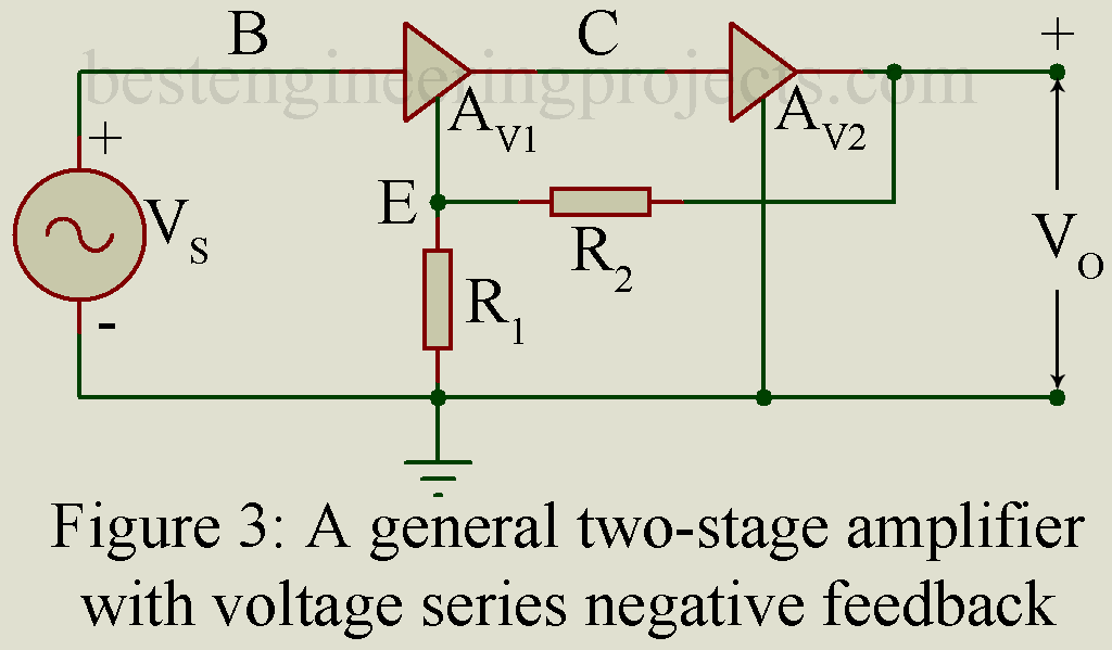
Figure 4 gives the circuit of a two-stage R.C. coupled CE Amplifier using negative voltage series feedback. The Collector of the second stage is connected to the emitter of the first stage through a voltage divider network R1 – R2.
In this amplifier,  . Hence,
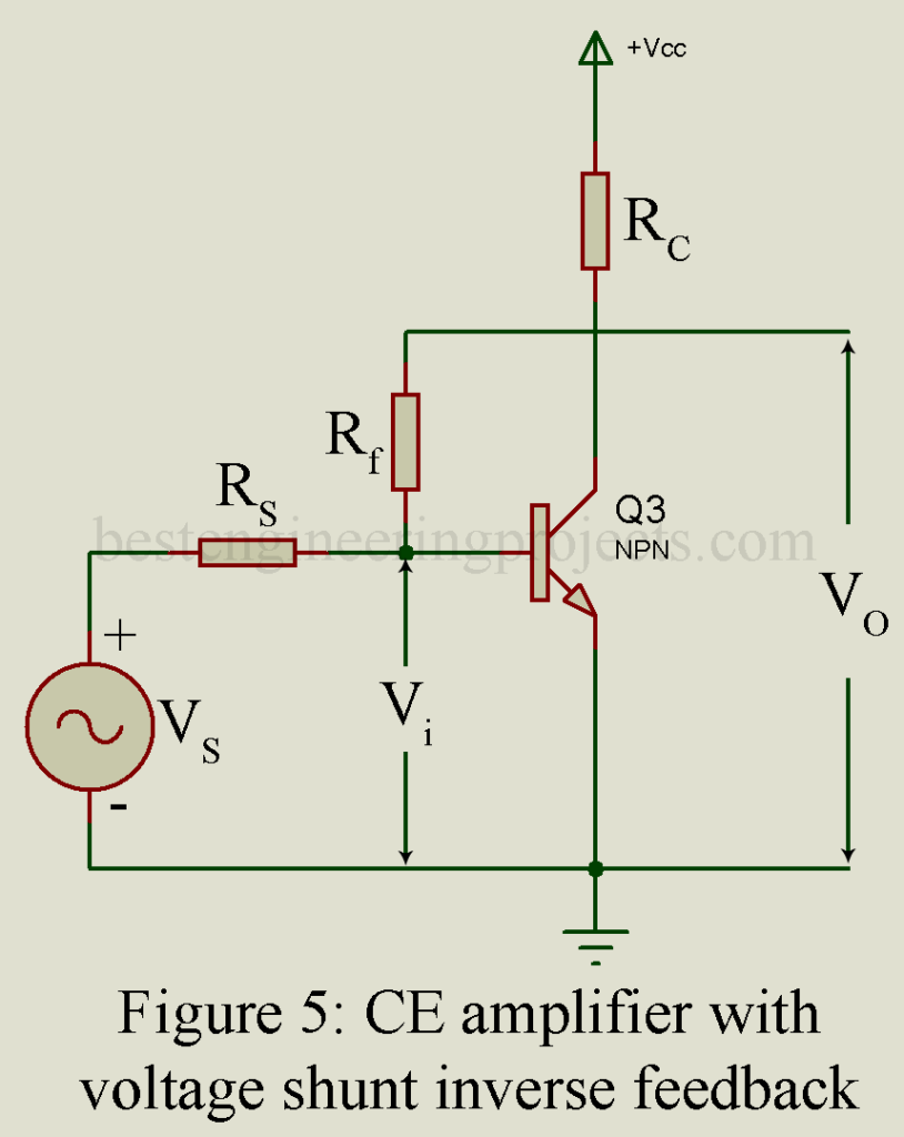
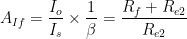
CE Amplifier using Voltage-Shunt Inverse Feedback
Figure 5 gives the circuit of a CE amplifier stage with a resistor Rf providing feedback from collector to base. Here the feedback is proportional to the output voltage and the feedback signal (current) gets added to the shunt with the input. Hence this circuit forms the case of a voltage-shunt inverse feedback amplifier.
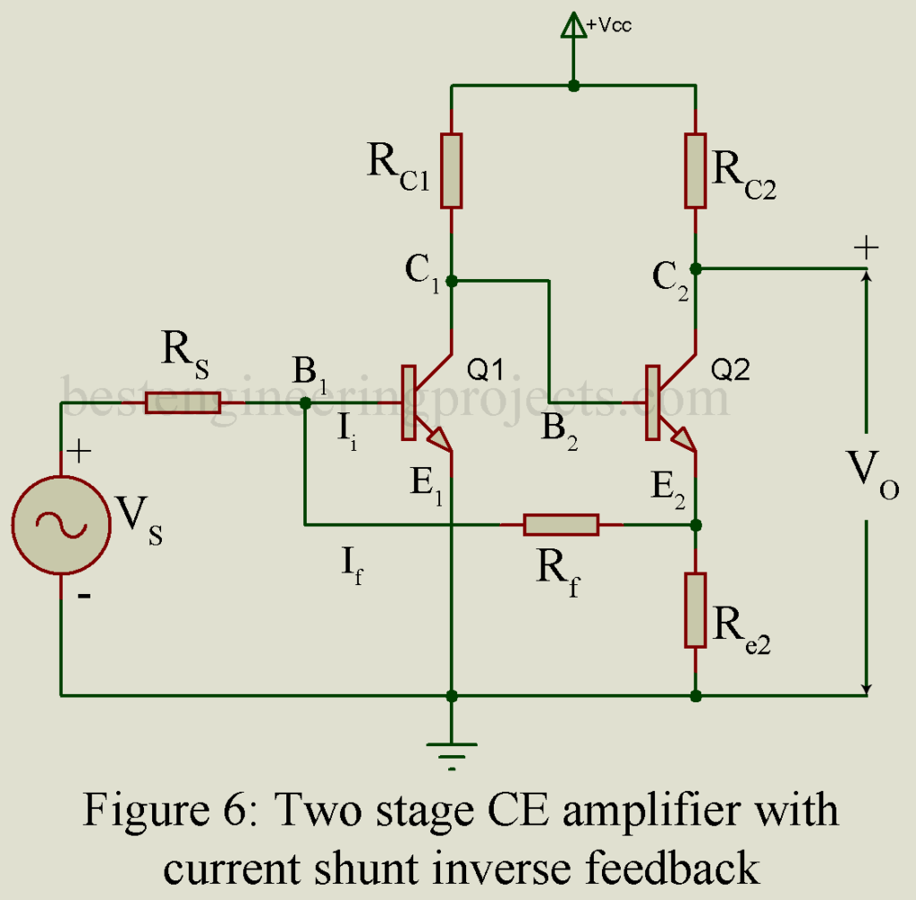
Two-Stage CE Amplifier with Current-Shunt Inverse Feedback
Figure 6 gives the circuit of a two-stage CE amplifier with current shunt inverse feedback. Here feedback is from the emitter of the second stage to the base of the first stage through resistor Rf.
Analysis shows that,
 …….(11)
And current gain with feedback is,
 ……….(12)
Voltage gain with feedback is
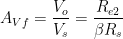 …….(13)
Typical Amplifiers using Current-Series Feedback
Here we consider the following two examples of amplifiers using current-series feedback:
- CE amplifier with a resistor Re in the emitter circuit
- FET common source (CS) amplifier with a resistor R in the source to the ground circuit.
CE Amplifier with Resistor Re in the Emitter-to-ground Circuit
Figure 7 gives the basic circuit. here the sampled signal is the load current Io while the feedback signal is the voltage Vf across Re. This feedback voltage Vf comes in series opposition with the input voltage Vs. hence this forms a case of current-series inverse feedback. Analysis shows that:
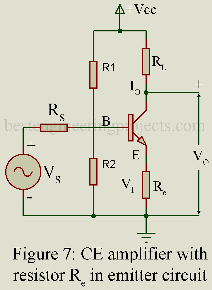
Analysis shows that:
 ……(14)
 …….(15)
 ………(16)
 ……..(17)
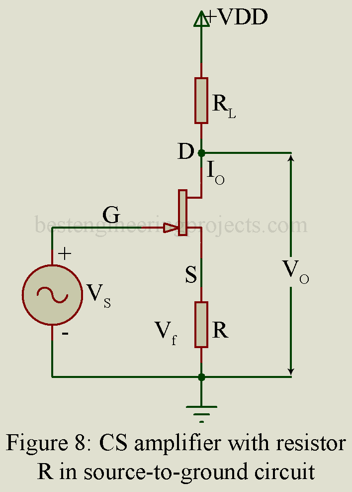
Common Source (CS) Amplifier with resistor R in source-to-ground circuit
Figure 8 gives the basic circuit. Here the load current Io forms the sampled signal while the voltage Vf across resistor R forms the feedback signal. This feedback voltage Vf comes in series opposition with the input voltage Vs. hence this forms a case of current-series inverse feedback.
Analysis shows that:
 …….(18)
 . Hence Rif is also infinite.
 ……..(19)