Automatic battery float charger circuit:
This article aims to develop a battery charger circuit using the principle float charging technique. Afloat charger is also referred to as a smart charger, maintenance charger, or storage charger because it charges the battery at the same rate at which it self-discharges.
The main reason for using a float charger is, that it protects the battery from overcharging and deep discharging. Thus, you can connect the float charger circuit to a battery for indefinite intervals of time i.e. there is no need to disconnect the charger circuit from the battery. The project ‘Automatic battery float charger circuit’ is designed to charge a 12V sealed lead-acid battery.
Description of Automatic Battery Float Charger Circuit:
The circuit is shown in figure 1. For description, we divided the entire circuit into three main sections.
Rectifier Section | Automatic Battery Float Charger Circuit
This section is designed around a step-down transformer and a bridge rectifier. We had used here 230V to 15V, 1A transformer which lower the AC mains to 15V AC. This step-down voltage (15V) is changed to pulsating DC using a bridge rectifier. The bridge rectifier is built around four rectifier diodes. Capacitor C1 filters the pulsating part of DC and smoothens the wave.

Current Limiter Circuit | Automatic battery float charger circuit
The current limiting circuit is built around the LM317 (IC1) variable voltage regulator IC. Here we had designed the current limiting circuit for 0.3 Amps because the datasheet of the battery recommended so. To design the current limiting circuit, we had to calculate the value of resistor R1.


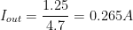
Generally, in the market the value of resistor 4.1667 is not available thus we had used the nearest value of resistor i.e. 4.7 .
If we had used 4.7 resistor the current limit to
Voltage Regulator Circuit | Automatic battery float charger circuit
Voltage regulator circuit is also build around LM317 variable voltage regulator IC. Let, the max charging voltage will be 13.75V and we had used a diode for blocking reverse voltage from battery, thus we had produce the output of 13.75V + 0.7V
Therefore 
The standard formula for calculation Vout is
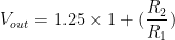
Here we had design the circuit for 14.45 thus we had to find the value of resistor R1 and R2


In order to get the value of 2320 we had made a series combination of 1.5 and 820 .
Therefore 


Automatic cutoff Section | Automatic battery float charger circuit
The circuit of the cutoff section is built around op-amp LM358. Op-amp LM358 is configured in comparator mode. Op-amp under open-loop operation is indeed a basic comparator circuit for comparing signals at its input terminals. The comparator can be used as a non-inverting or an inverting circuit. Here we had used an inviting circuit. For the operation, Vin is applied to the non-inverting input terminal of the op-amp and the reference voltage (VR) is connected to the inverting input. In this case, the comparator output will be in the ‘high’ (or 1) state (= + VZ) when (Vin – VR) > 0; and it will be in the ‘low’ or ‘0’ state (=-VD) otherwise.
When the battery is fully charged the relay becomes de-energized and vice-versa.
Relay Switching Circuit | Automatic battery float charger circuit
The switch is designed using an NPN transistor (BC547). When the battery is charged the transistor starts to connect and hence energized the relay. Similarly, when the battery is fully charged the transistor is switched off and hence relay is de-energized.
Transistor T2 is used because when the battery is not connected to the battery terminal 0V is appeared at inverting input. Hence, the output of op-amp becomes high. To avoid this condition, the PNP transistor grounds the base of BC547. Hence the output is entirely controlled.
Glowing LED1 indicates the power supply of the circuit.
Glowing LED2 indicates the battery is charging.
Glowing LED3 indicates the battery is fully charged.
Check out other various battery charger circuit posted in bestengineeringprojects.com
- 12 V Battery Charger with overcharge and deep-discharge protecting
- Ni-Cd Battery Charger
- 12v, 7Ah Smart Battery Charger with PCB Diagram
- Ni-Cd Battery Charger Circuit
PARTS LIST OF AUTOMATIC FLOAT CHARGER CIRCUIT
| Resistors (all ¼-watt, ± 5% Carbon) |
| R1 = 4.7 Ω, 2W
R2 = 220 Ω R3, R12 = 1.5 KΩ R4 = 820 Ω R5, R9, R10 = 1.2 KΩ R6 – R8 = 1 KΩ R11 = 750 Ω R13 = 10 KΩ |
| Capacitor |
| C1 = 1000 µF, 30V (Electrolytic Capacitor) |
| Semiconductors |
| IC1, IC2 = LM317 (Adjustable Three Terminal Positive Voltage Regulator)
IC3 = LM7805 (5 Volt Series Voltage regulator) IC4 = LM358 (Dual Operational Amplifier) T1 = BC547 (BJT NPN Transistor) T2 = 2N2907 (BJT PNP Transistor) D1 – D6 = 1N4007 (Rectifier Diode) LED1 = 5mm, Blue color LED LED2 = 5mm, Red Color LED LED3 = 5mm, Green Color LED |
| Miscellaneous |
| X1 = 230V to 15V, 1A Step Down Transformer
RL1 = 5V relay 12V, 3A Battery to be charged |