Introduction to Ni-Cd Battery Charger Circuits
Nickel-cadmium (Ni-Cd) batteries are commonly found in all sorts of household electronics and gadgets. Because these batteries go through frequent use and constant charging and discharging, having a dependable and efficient charger is essential. In this guide, we’ll walk you through a tried-and-true Ni-Cd battery charging circuit designed to safely recharge your batteries while including important protection features to keep everything running smoothly.
Features of the Ni-Cd Battery Charger Circuit
This Ni-Cd battery charger is designed to charge seven Ni-Cd pencil cells in series or a 9V Ni-Cd battery pack. It operates at a constant current of 50mA and includes safety indicators that detect reverse polarity, short circuits, high resistance, or low-voltage battery conditions, all signaled through two LEDs. After a 14-hour charging period, the circuit disconnects the battery and switches to trickle charging mode to prevent overcharging and maintain battery health. Additionally, an audible alarm sounds once the charging process is complete.
How the Ni-Cd Battery Charger Circuit Works
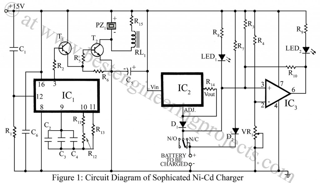
The Ni-Cd charger circuit is based on three primary components: a constant current source, a 14-hour timer, and a comparator circuit for battery monitoring.
- Constant Current Source for Ni-Cd Charging
This circuit uses an LM317 (IC2) to provide a stable constant current. By choosing the right value for the resistor R14, the output current is set to 50mA (using the formula I = 1.2V/R14). This setup keeps the charging process efficient no matter what the battery voltage is. To make sure the battery doesn’t discharge if there’s a power failure, diodes D1 and D2 are included for protection.
Resistor R7 and diode D2 work together to allow trickle charging, which means that once the battery is fully charged, a small current continues to flow, keeping the battery topped up without overcharging it.
14-Hour Timer Circuit for Charging Control
The timer circuit is managed by IC1 (CD4060), a 14-stage counter equipped with an oscillator. The oscillator frequency is set by F = 1/2.2RC, where R = R11 + R12 and C = C2 + C3 + C4. With the circuit values provided, the oscillator runs at 1/6 Hz, and pin 3 outputs a high signal after 14 hours, signaling the end of the main charging period.
At this point, a Darlington driver consisting of transistors T1 and T2 activates relay RL1, disconnecting the battery from the primary current source to prevent overcharging. At the same time, a buzzer rings, indicating that the battery is fully charged and ready for use. Capacitor C1 and resistor R1 automatically reset IC1 during power-on.
- Comparator Circuit for Battery Health Monitoring
The circuit uses IC3 to monitor the battery’s health. It keeps an eye on things by comparing voltages, with pin 2 set to 0.4V by VR1. Pin 3 is connected across the battery and usually stays linked to +Vcc through resistor R3. To keep the circuit stable and avoid any false readings, resistor R10 is added to introduce a bit of hysteresis.
Check out other various battery charger circuits posted on bestengineeringprojects.com
- 12 V Battery Charger with overcharge and deep-discharge protecting
- Ni-Cd Battery Charger
- 12v, 7Ah Smart Battery Charger with PCB Diagram
- Automatic battery float charger circuit
The table shows the conditions when different faults are detected.
|
Condition |
RED LED |
Yellow LED |
Indication |
|
1. |
ON |
OFF |
Normal battery charging |
|
2. |
ON |
ON |
There may be a reverse connection of the battery. Check whether the battery is connected correctly. If it is connected properly then the battery is short and is not usable. |
|
3. |
ON |
Remains “ON” for some time and then goes “OFF” |
Low voltage battery. Charging may be continued. |
|
4. |
Remains “ON” for some time and then goes “OFF” |
OFF |
High resistance battery. This indicates that the battery is not usable |
Modifying the Charger for 6V Lead-Acid Batteries
To charge a 6V lead-acid battery with this circuit, just change R14 to a 2.2Ω, 2-watt resistor. Also, make sure to attach a heatsink to IC2 so it can handle the extra current properly and not overheat.
Conclusion
This Ni-Cd battery charging circuit is super versatile and gives you a reliable, efficient way to charge all kinds of Ni-Cd battery packs.
The circuit is really easy to use, with built-in safety features, a trickle charging mode, and an alert sound to let you know when charging is done. It’s great for Ni-Cd batteries, but you can also adjust it for other types, like lead-acid. Plus, the constant current charging makes sure your batteries stay fully charged and last longer.
PARTS LIST OF NI-CD BATTERY CHARGER CIRCUIT
|
Resistor (all ¼-watt, ± 5% Carbon) |
|
R1 – R4, R6, R7 = 100 KΩ R5 = 1 KΩ R8, R9 = 1.5 KΩ R10, R11 = 1 MΩ R12, R13 = 3.3 MΩ R14 = 22 Ω/0.5W R15 = 33 Ω/0.5W VR1 = 100 KΩ linear |
|
Capacitors |
|
C1 = 0.01 µF (Ceramic Disc) C2 – C4 = 0.22 µF (Ceramic Disc) C5 = 220 µF, 25V (Electrolytic capacitor) C6 = 0.1 µF (Ceramic Disc) |
|
Semiconductors |
|
IC1 = CD4060 (Counter IC) IC2 = LM317T (Adjustable positive voltage regulator) IC3 = µA741CN (Operational Amplifier) T1, T2 = BC547 (NPN Silicon Transistor) D1 = 1N4001 (Rectifier Diode) D2 = 1N4148 (Signal Diode) LED1 = Red LED2 = Yellow |
|
Miscellaneous |
|
PZ1 = piezo buzzer PEC 27IH RL1 = 12V, 150Ω SPDT, relay |