Approximate h-model:
In the analysis of the transistor amplifier, we have as far used the exact h-model for the transistor. In practice, we may conveniently use an approximately h-model for the transistor which introduces an error of < 10% in most cases.
This much error may be conveniently tolerated since the h-parameters themselves are not steady but vary considerably for the same type of transistor. We first derive this approximate CE h-model.
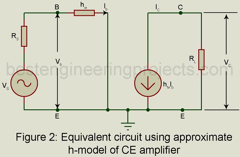
Figure 1 gives the equivalent circuit of the CE amplifier using the exact h-model for the CE transistor.
The following steps are used to drive the approximate h-model:
- If
 . If hoe. RL < 0.1, then we may neglected , being in parallel with RL.
 - Having neglected hoe, the collected current IC equals hfe. Ib and the magnitude of the dependent voltage generator in the emitter circuit are then given by,
 . If hoe. RL < 0.1, then we may neglected
  , being in parallel with RL.
 …..(1)

But  . Hence the voltage hre |VC | in the emitter circuit may be neglected in comparison with the voltage drop hie. Ib provided that RL is not very large. Then the approximate CE h-model reduces to the form shown in Figure 2.
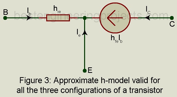
Approximate h-model Valid for all the three Configuration
The approximate CE h-model of Figure 2 is redrawn in figure 3. This model may be used for any of the three configurations by grounding the appropriate node and analysis done accordingly. It may be proved that the error in values of AI, Ri, AV, or output terminal resistance Rot (= R0 || RL) caused by the use of an approximate model does not exceed 10% if 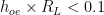 .
.
Analysis of CE Amplifier using Approximate h-model
Figure 2 gives the equivalent circuit of a CE amplifier using an approximate h-model for the transistor. For this equivalent circuit, we get,
Current gain 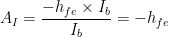 …..(2)
Input resistance 
Voltage gain  ……(3)
……(3)
Output resistance R0: From this approximate equivalent circuit of figure 1(b) with Vs = 0 and with an external voltage source connected across the output, we get Ib = 0 and therefore IC = 0. Hence output resistance  . However, in actual practice, R0 lies between
  depending on the value of RS.
With load resistance  (the maximum practical value), the output terminal resistance
Condition  For a typical transistor
 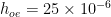 S. Hence to meet the condition that
 ![h_[oe] \times R_L < 0.1](https://s0.wp.com/latex.php?latex=+h_%5Boe%5D+%5Ctimes+R_L+%3C+0.1&bg=ffffff&fg=000&s=0&c=20201002) , we must use RL less than
, we must use RL less than  .
.
Analysis of CB Amplifier using the Approximate Model
Figure 4 gives the equivalent circuit of a CB amplifier using the approximate model for the transistor as given in figure 2 with the base grounded, the input applied between the emitter and base, and output obtained across load resistor RL between the collector and the base.
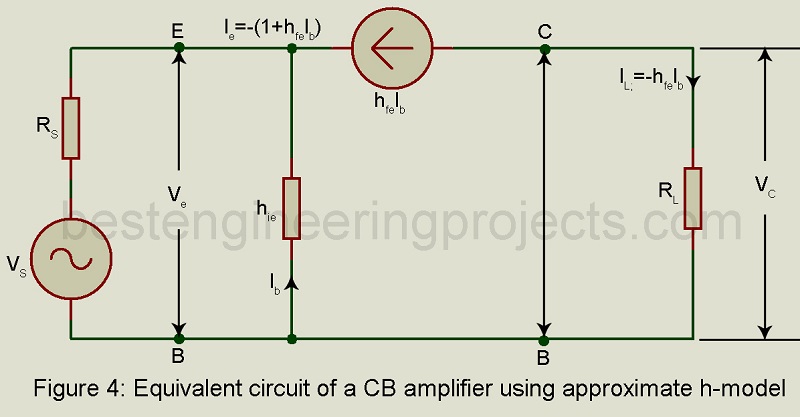
Current gain  …..(4)
Input resistance Ri: from figure 4,
 ……(5)
……(5)
 …….(6)
Hence,  …..(7)
Voltage Gain AV: From figure 4,
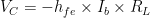
Hence, 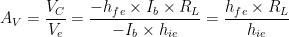 …..(8)
Output resistance In the equivalent circuit of figure 3, with Vs = 0, we get Ie = 0. Hence, Ib = 0. Hence the output resistance .
Output Terminal Resistance  …..(9)
Analysis of CC Amplifier (Emitter Follower) using Approximate h-model
Figure 5 gives the equivalent circuit of an emitter follower using the approximate model as given in figure 3, with the collector grounded, the input signal applied between the base and the ground, and the load impedance RL connected between the emitter and ground.
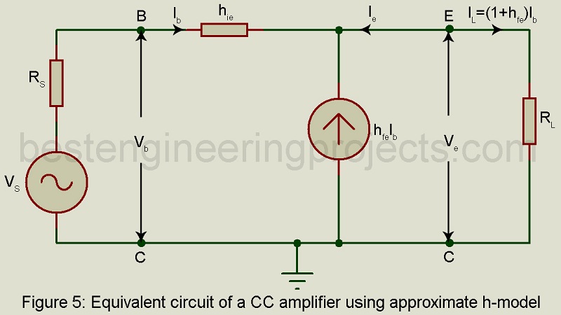
Current gain AI: from the circuit of figure 5,
Load current 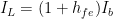 …..(10)
Hence Current gain  …..(11)
Input resistance Ri: from figure 5,
 …..(12)
Hence, 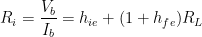 ……(13)
Voltage Gain AV: From figure 5,
 ……(14)
Hence, 


Output Resistance From figure 5, Open circuit output voltage = VS
Short circuit output current 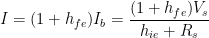
Hence output impedance 
Output terminal Impedance 
Table 1 gives expressions for current gain etc. for the three configurations using an approximate h-model.
| Table 1 Expressions for AI, Ri, AV, R0, and Rot using Approximate h-model | |||
| Quantity | CE | CB | CC |
| AI | -hfe |  |
1 + hfe |
| Ri | hie |  |
hie + (1 + hfe)RL |
| AV |  |
 |
 |
| R0 |  |
|
 |
| Rot | RL | RL | R0 || RL |
Where is figure 5? the model for cc amplifier
Hi iniyan, thankyou for letting us know.
Now, the article is updated with picture.
We have a little bit confusion about this topics now it will clarified.
Thank you sir