Discover how a woofer and tweeter matcher circuit enhances audio systems by producing balanced sound. Learn how specialized components optimize low and high frequencies, leading to an enjoyable listening experience.
Introduction:
A speaker’s frequency response plays a crucial role in delivering high-quality sound across the audible spectrum. However, not all speakers can reproduce frequencies uniformly, leading to an imbalanced sound output. To overcome this challenge, audio systems incorporate specialized components known as woofers and tweeters, each optimized for handling specific frequency ranges.
Woofer and Tweeter Function:
Woofer: A woofer is specially designed to handle low-frequency sounds, encompassing bass and midrange frequencies. With its larger size and placement in the main speaker cabinet, the woofer effectively moves more air, resulting in powerful and accurate low-frequency reproduction.
Tweeter: The tweeter, on the other hand, excels in handling high-frequency sounds, including treble frequencies. It’s smaller size and strategic placement on the top or center of the speaker cabinet allow it to produce crisp and clear high-pitched sounds, such as vocals, cymbals, and other instruments with high-frequency content.
Challenges with Direct Amplifier Signal:
Directly sending the amplifier’s signal to either the woofer or tweeter without processing can lead to undesired sound output. Since the amplifier’s output covers the full range of frequencies, the woofer may struggle to handle both low and high frequencies, resulting in distortion and poor sound quality. Similarly, sending the entire frequency range to the tweeter can cause difficulties in reproducing bass frequencies, potentially leading to warping and damage.
The Role of Matcher Circuit:
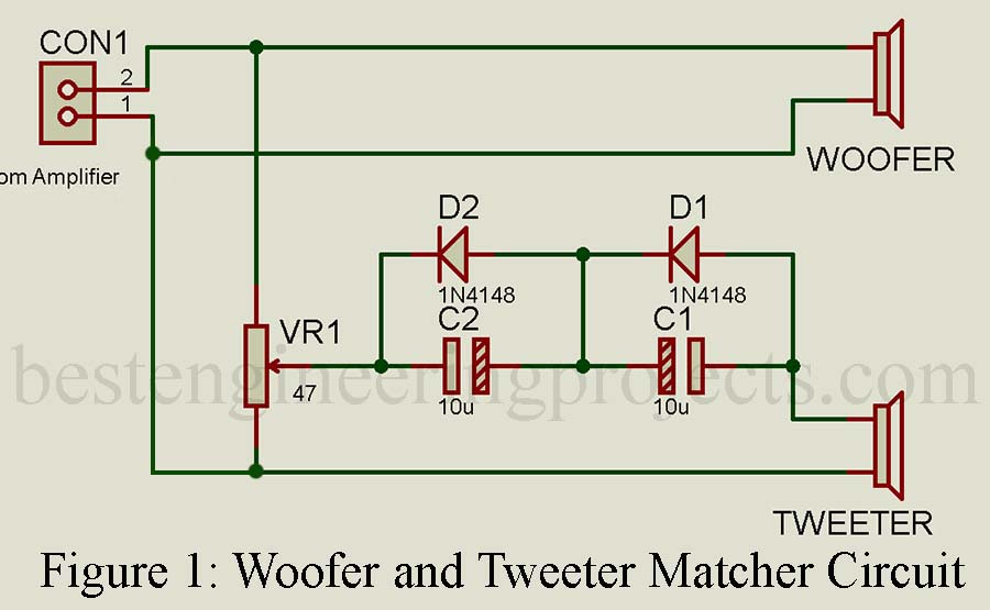
To address the challenges associated with the direct amplifier signal, a matcher circuit, acting as a crossover network comes to the rescue. This ingenious circuit divides the amplifier’s full frequency range into appropriate bands for the woofer and tweeter, ensuring each component operates within its optimal frequency range.
How the Matcher Circuit Works:
The matcher circuit incorporates a few essential components, including two diodes, two capacitors, and a variable resistor (potentiometer). These elements work together to create frequency filters, effectively directing specific frequency ranges to their corresponding components.
The variable resistor, often labeled VR1, offers the advantage of fine-tuning the sound balance between the woofer and the tweeter. This customization ensures a harmonious distribution of frequencies, resulting in a well-balanced and accurate sound reproduction.
The woofer and tweeter matcher circuit plays a pivotal role in audio systems, optimizing the performance of both woofers and tweeters. By expertly dividing the amplifier’s signal into appropriate frequency bands, this circuit ensures an enhanced and enjoyable audio experience. With clear bass, midrange, and treble frequencies, listeners can immerse themselves in the full richness of sound, making their audio journey truly unforgettable.
Component List of Woofer and Tweeter Matcher Circuit
| Resistor (all ¼-watt, ± 5% Carbon) |
| VR1 = 47 Ω |
| Capacitors |
| C1, C2 = 10 µF/25V (electrolytic) |
| Semiconductors |
| D1, D2 = 1N4148 |
Interesting circuit. The woofer is a closed circuit, however, you have an open circuit for the tweeter – no return path back to terminal 1 – likely a typo. You should repost the corrected circuit.
Thank you Pete, we had updated the circuit.