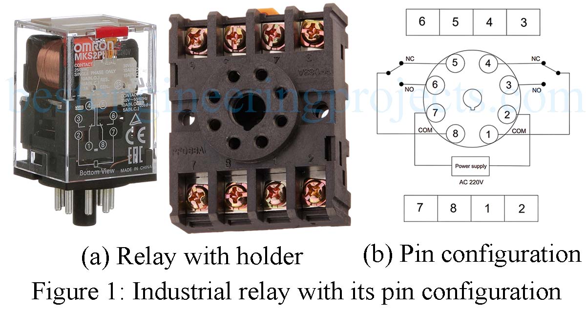
Upon reading this article, users will understand industrial relays comprehensively, including their pin configuration and Relay Latching Circuit switching mechanisms. A relay is an essential electromechanical switch, consisting of a coil as its electrical component and contacts as mechanical components. It plays a pivotal role in industrial automation, facilitating switching operations and logical control. The relay discussed in this article is a 10A, 220V AC DPDT industrial-type relay, with a coil voltage of 220V AC. It features two poles, each equipped with a Normally Closed (NC) and Normally Open (NO) pin, capable of continuously handling 10A of current. Figure 1 shows the Relay, its base, and its pin configuration.
One-point control circuit
The relay remains energized as long as it receives a supply voltage to its coil. This type of control is called one-point control, as it relies on a single switch to turn the relay on and off. Typically, a selector-type switch is used in this setup, maintaining the coil voltage until the relay needs to be energized. To stop the relay, the supply voltage is cut by changing the position of the switch. The circuit diagram of the one-point control circuit is shown in Figure 2.
 Figure 2: One point Control of Relay
In this configuration, a momentary push switch is unsuitable since the relay would energized only as long as the switch is pressed.
Relay Latching Circuit
To enable operation from two points, with a dedicated stop switch, a latching or holding logic is required. This type of control circuit is also known as a two-point control circuit because it can be controlled from two points, featuring a dedicated start switch and a stop switch. The switch employed for this purpose is a momentary-type push button.
 Figure 3: Relay Latching Circuit
Circuit Description:
The circuit is straightforward and easy to comprehend. Because it operates from two points, it requires two switches, one for starting and the other for stopping. The stop switch is always connected in series, usually preceding the start switch. The stop switch is a Normally Closed (NC) push button, which means it is normally in a closed state and becomes open when pressed. Following the stop switch, the start switch is connected. The start switch is a Normally Open (NO) push button, requiring a press to close. One terminal of the start switch is linked to the stop switch, while the other is connected to one terminal of the relay coil. To latch the relay, the common pin and the corresponding NO pin of the relay are connected in parallel to the start switch, as shown in the circuit diagram.
Working of the Relay Latching Circuit:
Initially, the relay is in a de-energized state. However, when the start switch is pressed, voltage is supplied to the relay coil, causing the relay to energize and remain in that state even after the start switch is released. After releasing the start switch, voltage continues to be supplied to the relay coil through the latching circuit, involving the relay’s common (COM) pin and NO pin. When the stop switch is pressed, it interrupts the power supply to the coil, resulting in the de-energization of the relay.
For added safety, an emergency switch can be incorporated into the circuit, connected in series, similar to the stop switch.
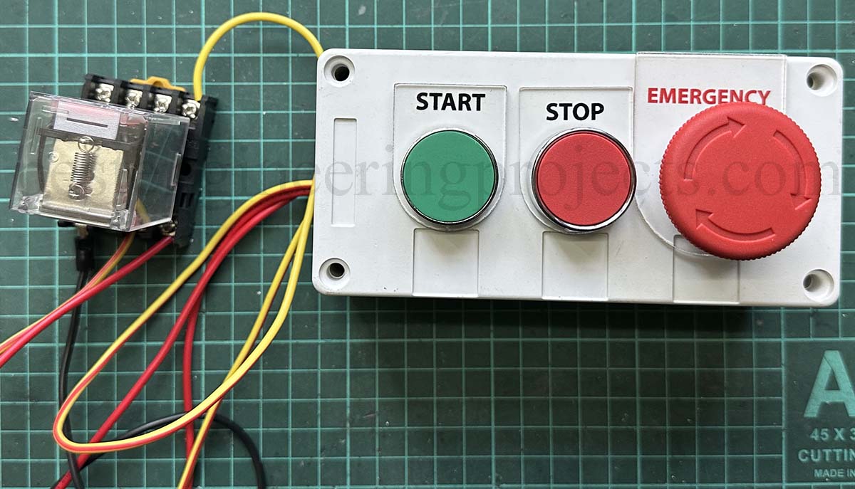 Figure 4: Relay Latching Circuit Prototype