Today in this tutorial we will see the interfacing optocoupler with Arduino (4N35 or MCT2E). Optocoupler is also called an optoisolator. But before that let’s see what an optoisolator or optocoupler is?
What is Optocoupler or Opto-Isolator:
Optocouplers or optical isolators are designed to electrically isolate one circuit from another while allowing one circuit to control the other. The usual purpose of isolation is to protect from high-voltage transient, surge voltages, and low-level electrical noise that could result in an erroneous output or damage to the device. Such isolators allow circuits to interface with different voltage levels and grounds, etc.
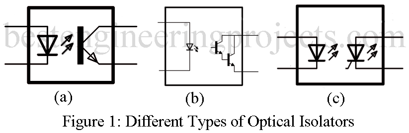
An optocoupler or optical isolator consists of a light source such as LED and a photodetector such as a phototransistor as shown in figure 1(a) and is available in a standard IC package.
When LED is forward-biased, the light produced by it is transferred to the phototransistor when is turned ON thereby producing current through the external load.
Figure 1(b) shows a Darlington transistor coupler which is used when increased output current capability is needed beyond that provided by the phototransistor output. The LASCR output coupler for figure 1(c) can be used in applications where a low-level input voltage is required to latch a high voltage relay for activating some kind of electro-mechanical device.
There are various reasons for using Optocoupler for switching, some are listed below
- It provides isolation between the control circuit and power switching and saves the control circuit from high-voltage transient or surge voltage usually generated from Inductive load like Motor, relay, etc.
- A microcontroller cannot drive a relay directly because the required current for driving the relay is much more than the current supplied by the microcontroller. You can also check “How to make Relay Switch Circuit”.
- Normally, the Gate to Source voltage (VGS) of MOSFET or IGBT is greater than 5V so we cannot trigger the gate directly from the microcontroller. For this purpose, we can use an optocoupler.
Circuit Description of Interfacing Optocoupler with Arduino
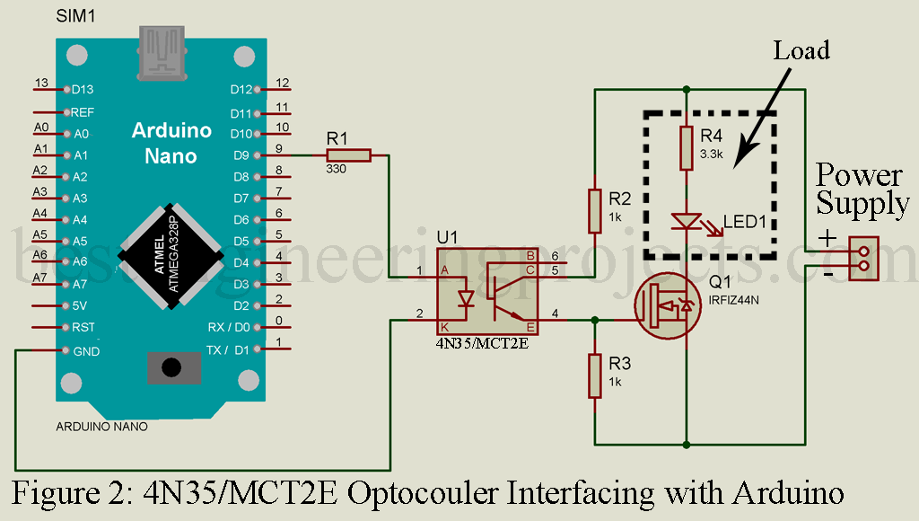
The circuit of Arduino and optocoupler interfacing is shown in figure 2. It is built around Arduino NANO, MCT2E Optocoupler, MOSFET, resistor, and other few components. MCT2E is 6 pin optocoupler but here we are using only 4 pins as shown in the figure. Pin 1 of MCT2E i.e. Anode is connected to PWM pin 9 of Arduino PWM (you can use any other PWM pin or other according to your requirement). The reason for using a PWM pin is to vary voltage but you can use a digital pin instead according to your requirement. One current limiting resistor is connected between Arduino pin 9 and optocoupler pin 1 to protect LED from burnout.
Let’s calculate the value of the resistor
Forward voltage of 4N35 = 1.2V
Forward current of 4N35 = 10mA
Input voltage (from arduino) = 5V
Voltage difference = 5V -1.2V = 3.8V
This is the voltage dropout by a resistor to protect the LED of the optocoupler now let’s calculate the value of the resistor using Ohm’s Law


R = 380-ohm is the minimum value of the resistor we have to use on the input side. You can also use a higher value of the resistor but not a lower one.
The current limiter on the other side depends upon your circuit and operating voltage. The positive power supply is connected to the collector (pin 5) of the optocoupler where the emitter is connected to the gate of MOSFET. One pull-down resistor is connected between the gate and ground to avoid false triggering.
NOTE: Do not connect the ground of the control circuit and switch circuit together. i.e. both the ground must be ISOLATED.
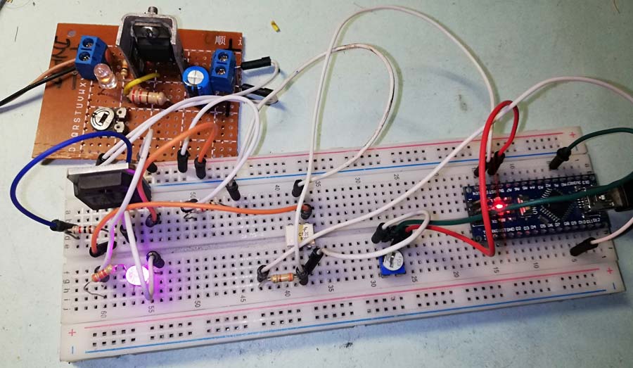 Figure 3: Author Prototype of Interfacing Optocoupler with Arduino
Component List of Interfacing Optocoupler with Arduino
Arduino NANO x 1
MCT2E or 4N35 x 1
330-ohm Resistor x1
1k-ohm Resistor x 2
3.3k-ohm Resistor x 1
IRFIZ44N MOSFET x 1
LED x 1
Software Code:
|
1 2 3 4 5 6 7 8 9 10 11 12 13 14 |
int led_pin = 9; int led_value; void setup() { pinMode(led_pin, OUTPUT); } void loop() { //from 0 to 255 using the analogwrite funtion led_value = 200; // change the value according to your requirement analogWrite(led_pin, led_value); delay(1); } |