The circuit diagram of the sound detector circuit using op-amp 741 is shown in figure 1. The heart of the circuit is op-amp 741 which is used in order to sense the vibrations of sound waves condenser microphones.
Introduction of Sound detector circuit using op-amp 741
Sometimes due to lack of concentration and our ignorance, we are unable to hear anything around us. And, that could lead to unfortunate misfortunes which could have been avoided with appropriate precautions. This circuit called ‘Sound Detector’ is what detects vibrations of the sound waves and amplifies them to be heard distinctly by human ears. As per the design of the sound detector circuit using 741 IC, it works efficiently within the 6 meters limit around the vicinity where it is fixed. This setup can be done in any desirable places like car porches and at the corners of the house. As soon as a microphone incorporated in the project detects sound wave vibration, the sound detector circuit using op-amp 741 produces beep sounds to alert people around that area.

Circuit Description of sound detector circuit using op-amp 741
The circuit diagram of the sound detector circuit using op-amp 741 is shown in figure 1. The heart of the circuit is op-amp 741 which is used in order to sense the vibrations of sound waves condenser microphones. The sensitivity of the condenser microphone is adjusted by the value of resistor R1 used in the circuit. Once the microphone detects sound vibrations, it picks them up and converts them into electrical signals. The output of the microphone is fed as input to pin 2 of IC1 via coupling capacitor C1. Then the signal undergoes amplification and it is forwarded to IC2(IC 741C) which in this project serves as a comparator device.

The non-inverting pin 3 of IC2 receives input from the amplified output signal of IC1 through another capacitor C2. In the same way, an inverting pin 2 of IC2 fetches input signal from a reference voltage passed via voltage controller VR2.
At the final stage, IC2 output is fed as triggering input pulse to Darlington pair transistors T1 and T2. A piezo-buzzer which is connected at the end of transistor T2 i.e. at the emitter terminal is that component responsible to produce beeping sound at the end of operations followed throughout the entire circuit.
The fascinating fact about the project sound detector circuit using op-amp 741 is that it can be designed within a small area on a PCB or Veroboard as well. To attain maximum possible gain of IC1 and sensitivity of IC2, adjust the respective values of potentiometer VR1 and VR2 as stated in the earlier paragraphs.
During practical implementations of the project, if the beeping sound from the piezo-buzzer goes on and on and doesn’t stop, set the wiper of VR2 towards the ground line. For faultless circuit, follow the instructions given below:
Fix the piezo-buzzer at a place where people can hear and sensor at an appropriate place where you need continuous monitoring.
So as to extend the sensitivity of the microphone, connect it using a two-core shielded wire and enclose it in a small case.
To avoid noises from AC mains, battery supplies are highly recommended for this particular project.
PCB Design for Sound Detector Circuit:
The PCB diagram is designed using Proteus 8.1. The solder side PCB and Component side PCB is shown in figure 2 and 3 where the PCB prototype is shown in figure 4. Download the PCB PDF file from the link given below. The picture shown here is scaled in 200%, for the exact size of PCB download the PDF file from the link.

Figure 2: Solder side PCB
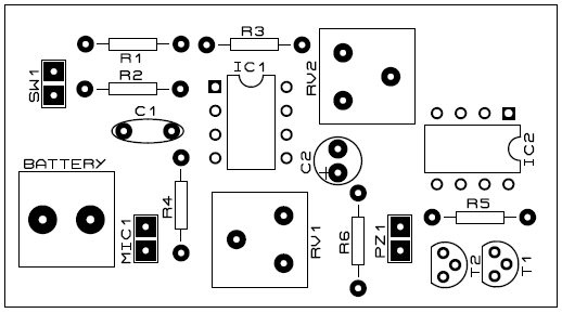
Figure 3: Component Side PCB
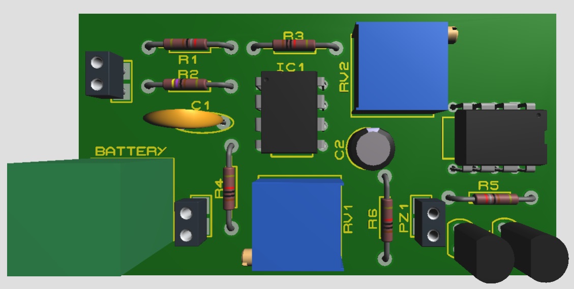
Figure 4: PCB Prototype for Sound Detector
Click Here to Download the Actual size PCB Diagram
PARTS LIST OF SOUND DETECTOR CIRCUIT USING OP-AMP 741
| Resistors (all ¼-watt, ± 5% Carbon) |
| R1 = 2.8 KΩ
R2 = 4.7 KΩ R3, R4, R6 = 10 KΩ R5 = 1 KΩ VR1 = 1 MΩ VR2 = 100 KΩ |
| Capacitors |
| C1 = 0.47 µF (Ceramic Disc)
C2 = 10 µF/16V (Electrolytic capacitor) |
| Semiconductors |
| IC1, IC2 = LM741C (Operational Amplifier)
T1, T2 = BC548 (General Purpose NPN Silicon Transistor) |
| Miscellaneous |
| MIC1 = Condenser Microphone
PZ1 = Piezo Buzzer SW1 = On/Off Switch 9V battery |
Hello. Are there any reasons why you used R6 between two transistors of the Darlington pair? I simulated the circuit and it sounds like the resistor added additional voltage drop to the Darlington pair. Are there other reasons?
Sorry, there was a mistake. I had update the circuit, here R6 is used to response on small signal.
is this circuit is updated inform quickly???
Brother response quick b/c i have submit this project tomorrow..
i connected this exactly as shown..but buzzer doesn’t produce any sound at all. only when I change(rotate) the VR1 does it produce continuous ringing (even without any sound). Any suggestions? Are we supposed to any other DC input to this?
Plz tell me the circuit diagram is uptodate or previous ?
Plz response fast i want this circuit in my project ???
Instead of ceramic is there any other capacitor can be used..and in the picture video you have shown there are three capacitor but in circuit there are only two capacitor..