Here is a 12V, 7Ah smart battery charger circuit which is also referred to as a smart charger uses three-stage of charging i.e. bulk stage, absorption stage, and float stage.
Normal battery charger technology uses single-stage battery charging technology i.e. only charge the battery up to the maximum charging voltage preset by the charging circuit. Now here is a 12V, 7Ah smart battery charging circuit which is also referred to as a smart charger uses three-stage of charging i.e. bulk stage, absorption stage, and float stage.
You may also like Arduino Controlled 12V battery charger circuit
80% of the charge is done in the bulk stage where the current is constant but voltage is increased. Similarly, the rest of 20% of the charge is done in the absorption stage (14.1VDC to 14.8VDC, depending upon the voltage set for sealed-lead-acid (SLA) 12V, 7Ah battery). Whereas the float stage occurs when the charge voltage is reduced to between 13.0 VDC to 13.6 VDC and currently does not drop, also this stage is used to maintain a fully charged indefinably.
Circuit Description 12v, 7Ah Smart Battery Charger with PCB Diagram
The circuit diagram of the 12V, 7Ah smart battery charger is shown in figure 1. It utilizes a step-down transformer, adjustable voltage regulator IC (LM317), op-amp comparator, zener diode, and a few other active and passive components.
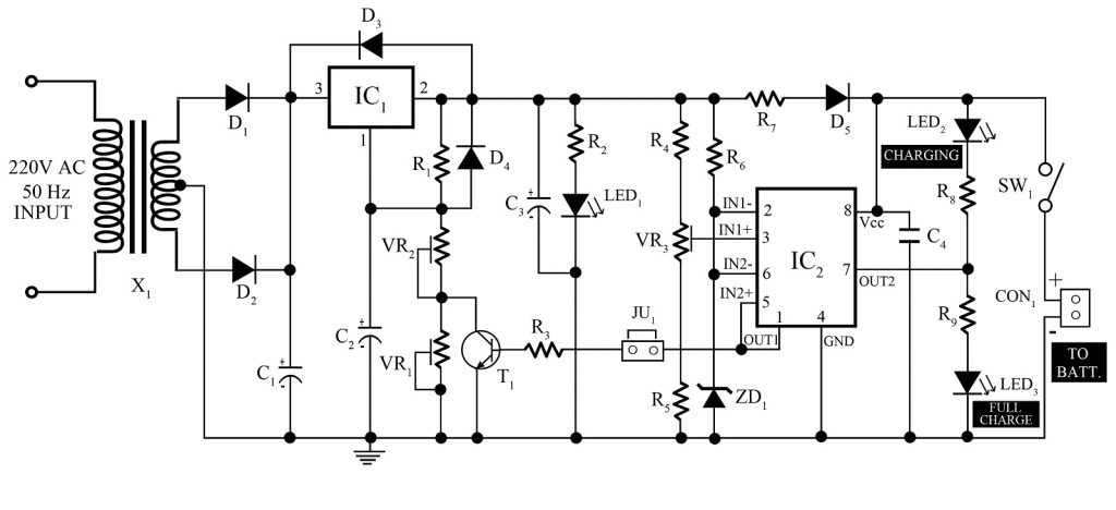 Figure 1: Circuit diagram of Smart Battery Charger
The input 220 Volt AC is step-down to 15V-0-15V using a center-tapped transformer. The step-down voltage is changed to pulsating DC with the help of a full-wave rectifier (D1 and D2) and is smoothed by capacitor C1. This voltage is further given to the input pin (pin 3) of the adjustable voltage regulator (IC1).
The output voltage obtained from the adjustable voltage regulator is determined or controlled by changing resistance at pin 1 of IC1. Check out the article on how to make a digital adjustable power supply using LM317.
Here, we used dual operation amplifier LM358 (IC2) as a comparator which compares the output voltage with a reference voltage and controls the overcharge of the battery. The LED1 is used to indicate power whereas LED2 and LED3 are used to indicate charging and fully charged the battery respectively.
Calibration of 12v, 7Ah Smart Battery Charger with PCB Diagram
For calibration or setup, remove the jumper and reconnect it back after calibration.
- Adjust potentiometer VR2 to get 13.6V at the cathode of diode D5 or Vcc (pin 8) of IC2.
- Adjust VR1 to get 0.5V (difference of output i.e. 14.1V-13.6V = 0.5V) at collector of transistor T1.
- Adjust VR3, so that the charging LED (LED2) starts to glow.
- Again adjust VR2 to get 14.1V at the cathode of diode D5 or Vcc (IC2) of IC2.
- The voltage at the jumper should be either 14.1 V or 13.6V depending upon the voltage at the cathode at D5. If the voltage at the jumper is 14.1V then the voltage at the cathode must be 13.6V and vice-versa.
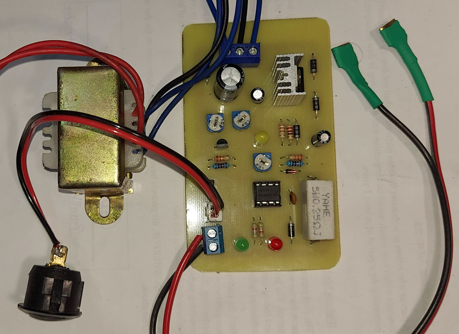
Figure 2: Author prototype of 12V 7Ah Smart Battery Charger
BEP NOTE on 12v, 7Ah Smart Battery Charger with PCB Diagram: –
- Must use good heat for the adjustable voltage regulator IC LM317 (IC1) and it must not be connected to the ground.
- Capacitor C4 should be kept as far as possible to pin 1 of IC2.
- For calibration jumper, JU1 must be removed and put back after calibration.
- The battery must be connected with the right polarity to the connector CON1.
PCB Diagram:
PCB of this smart battery charger circuit is built using the Altium design tool. Solder side and component side PCB diagrams are shown in Figures 3 and 4. Download the actual size solder side and component from the link given below.
Note: This PCB is originally designed for a 2N2222 transistor. If you prefer to use a BC547, simply rotate the transistor 180 degrees before soldering. The pin configuration of the BC547 (EBC) is the reverse of the 2N2222 (CBE), so rotating it will align the pins correctly without any need to modify the PCB layout.

Figure 3: Solder side PCB
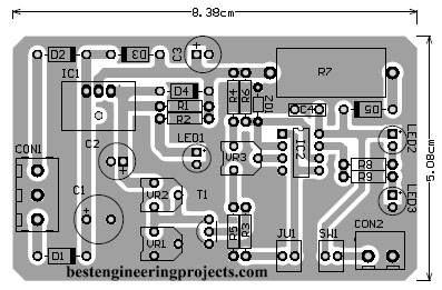
Figure 4: Component side PCB
Click here to download PCB LAYOUT
If you wish to design your battery charge indicator there here is a circuit for you.
10 Level Battery Charge Indicator Circuit
Check out other various battery charger circuits posted on bestengineeringprojects.com
- 12 V Battery Charger with overcharge and deep-discharge protecting
- Automatic Lead Acid Battery Charger Circuit
- 12V Lead Acid Battery Charger Circuit
- Automatic battery float charger circuit
- Arduino Controlled 12V Battery Charger Circuit
PARTS LIST OF 12v, 7Ah Smart Battery Charger with PCB Diagram
| Resistors (all ¼-watt, ± 5% Carbon) |
| R1 = 270 Ω
R2 = 2.2 KΩ R3, R6 = 10 KΩ R4, R5 = 22 KΩ R7 = 0.2Ω, 5W R8, R9 = 4.7 KΩ VR1 = 2 KΩ VR2 = 5 KΩ VR3 = 20 KΩ |
| Capacitor |
| C1 = 2200 µF/40V (Electrolytic Capacitor)
C2, C3 = 10 µF/25V (Electrolytic Capacitor) C4 = 0.1 µF (Ceramic Disc) |
| Semiconductors |
| IC1 = LM317 (adjustable three-terminal positive-voltage regulator)
IC2 = LM358 (low power dual operational amplifier) ZD1 = 6.8V Zener Diode T1 = BC547 or 2N2222 (NPN bi-polar junction transistor) D1 – D5 = 1N4007 (Rectifier Diode) LED1 – LED3 = 5mm LED |
| Miscellaneous |
| X1 = 230V AC primary to 15V-0-15V, 1A secondary transformer
CON1 = 2-pin connector terminal JU1 = 2-pin connector for jumper SW1 = On/Off Switch Heat sink for LM317 |
What is the output current of this circuit? I want to charge two (2) SLA batteries connected in parallel. How i can increase output to 1.5A ?
Though TO-220 plastic package can deliver up to 1.5A, but you can use metal can package of LM317 in order to get higher ampere (3A). If you want to increase output than replace the diode D1, D2 and D5 with higher current rating diode. And also check for the series resistor (R7), if it get hotter than also replace it with higher power (10W).
when calibrating should the battery be connected to the CON1 and the input power turned on? or Just then Input power and not the battery?
should the battry and input power connected and turned on when calibrating?.. or just the input power?
For calibration connect the power supply, no need to connect the battery.
Forgot to mention, i have dc source of 18v 7a. Can you be more specific about d5 ehich diode should i use to get 1.4a.
You can use any of these diode 1N5391, 1N5392, 1N5393, 1N5394, 1N5395, 1N5396, 1N5397, 1N5398, 1N5399.
It’s Maximum average forward rectified current is 1.5A.
Can I use 50K trim pot for VR3 instead of 20K.. The store didn’t have 20K trim pot so I bought 50K instead.. does it affect the circuit in anyway?
Yes you can use but the most tricky part is adjustment. For that you have to adjust properly.
I want to use this circuit for charging 2 of my SLA 12v 7ah battery in parallel and I have couple of questions…
Q1) I have a 24v transformer 2 wire ( around 3A i believe) .. can i use this 24V transformer instead of 15v transformer?.. I know the rectified voltage will be around 30v dc. I am planning to use it with a 6A bridge rectifier(BR68) and 4700uF 50V capacitor. since i already have the 24v transformer, rectifier and capacitor, I was wondering if i could use this so that i can save some money from buying a 15v 5A transformer.
Since I want to charge 2 batteries in parallel Can I change LM317 with L350 which has a 3A rating and the pinout configuration is same and also R7with 1N5822 3A schottky diode.
Yes you can use 24V transformer with bridge rectifier and L350 variable voltage regulator. Purpose of resistor R7 is to limit current. So I suggest you to add a current limiting resistor with schottky diode same as above circuit.
yes i meant to type replace D5 with 3A schottky diode not R7.. I accidently typed R7.. Thank you :)
vr1 has only one terminal conected to circuit? i see it that way in layout
Hi markos, One fixed terminal and variable terminal are shorted together. So that resistance varies when we rotate the wiper.
Hi ZD1 of 6.8v what wattage can be? Can u give me seroes model to look for please?
You can use 0.5W zener diode.
The charge and full keeps turned on at the same time when it’s close to full charge (or maybe charged) and the charging led doesn’t turn off.. I tried calibrating it multiple times and I am using 3296 multi turn precision trim pot and I am charging two 7ah batteries in parallel. using LM350K instead of 317 for 3A capability.. Input is 24V Transformer
Before calibrating please connect all components as shown in cirucit and than Please follow the steps for calibration.
it’s on a pcb i fabricated connections and components are correct.
sir i want 18vdc to 14vdc regulating supply for lead acid battery charging.
Do we have remaining terminals to ground?
I think BC547 is not in right direction in PCB layout plz … Guide me
Thanks, Ahsan Ali! Yes, you’re absolutely right. This PCB is originally designed for the 2N2222 transistor, but if you want to use a BC547, you can simply rotate it 180 degrees when soldering. The BC547 has an opposite pin configuration (EBC) compared to the 2N2222 (CBE), so this rotation aligns the pins correctly without needing any changes to the PCB layout. Thanks for highlighting that!
According to PCB layout collector is ground instead of emitter. Pl. Guide anyone.
Thanks, Ahsan Ali! Yes, you’re absolutely right. This PCB is originally designed for the 2N2222 transistor, but if you want to use a BC547, you can simply rotate it 180 degrees when soldering. The BC547 has an opposite pin configuration (EBC) compared to the 2N2222 (CBE), so this rotation aligns the pins correctly without needing any changes to the PCB layout. Thanks for highlighting that!