In the field of networking, RJ45 is the most common cable used. This cable consists of multiple wires clamped within a single plastic tube and in such a case, there is a high probability that the project implementing RJ45 will not work efficiently. Rather than isolating the entire circuit to check the fault, it is considered wiser to test the RJ45 cable which causes failure most of the time. And, here is the tester circuit called “RJ45 Cable Tester Circuit” which is used to test RJ45 cable either in straight-through or crossover-type.
The project RJ45 Cable Tester Circuit shown below have a sequence of LED which glow in a different sequence for different connection as shown in table 1.
|
TABLE 1 |
|
|
Sequence for straight-through and crossover cable |
|
|
Straight-through |
Crossover |
|
LED1 |
LED2 |
|
LED2 |
LED3 |
|
LED3 |
LED1 |
|
LED4 |
LED4 |
Circuit Description and Working of RJ45 Cable Tester Circuit
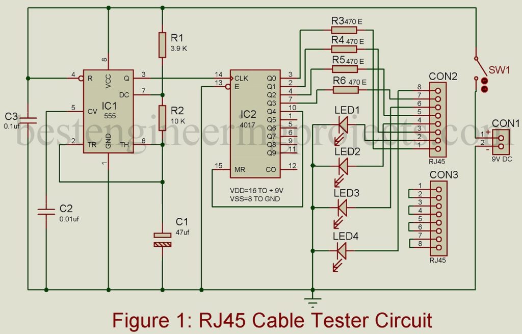
The circuit of the RJ45 tester circuit is shown in figure 2 and is built around the most popular timer IC NE555 and a decade counter IC CD4017B. Here in the project RJ45 tester circuit timer IC NE555 is configured in astable multivibrator mode which is designed to generate a 1 Hz clock pulse at its output pin (pin 3). The output of IC1 (pin 3) is connected to clock pin 14 of IC2 which provides the necessary clock pulse.
The output is taken from pin Q0 to Q3 (pins 3, 2, 4, and 7) which drives the LED sequence. This output is connected to CON2 (RJ45 socket), through which clock pulse is sent and the returning pulse is connected to the LED sequence as shown in figure 2. Simply, these wire is treated as a transmission path for clock pulse. The resistors R3 through R6 are used here as a current limiting resistor which limits or drops the current flowing through individual LED. The Reset pin (pin 15) of IC2 is connected to its output pin Q4 (pin 10). This is because the fifth clock pulse it will reset the decade counter IC (IC2).
If the RJ45 cable which is under test is straight-through the LED1, LED2, LED3, and LED4 will glow in sequence. Similarly, for Crossover types, LED2, LED3, LED1, and LED4 will glow in sequence.
The cable which is to be tested is connected to the two connectors CON2 and CON3 and observe the sequence of glowing LED.
Click Here To Download PCB Design
Construction and Testing of RJ45 Cable Tester Circuit
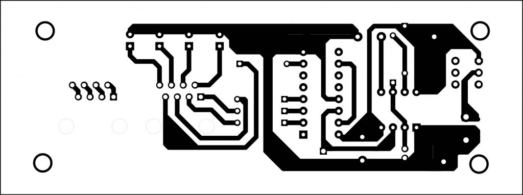
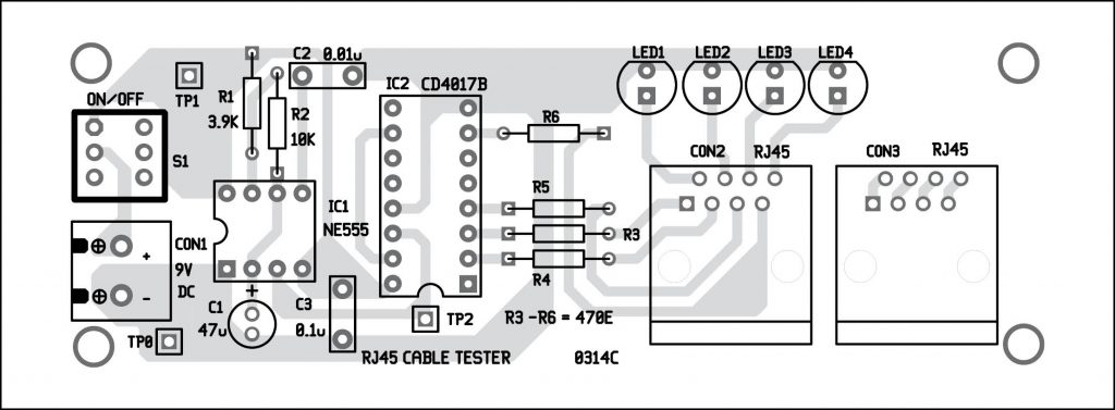
Figure 2 shows the actual-size, solder side PCB design for RJ45 Cable Tester Circuit. Figure 3 depicts a component side of RJ45. As shown in figure 2 RJ45 Cable Tester Circuit places all the components in the assigned order and avoids any possible errors which may degrade the implementation process. Once the assembling process is completed, check for possible errors and then provide the circuit with a 9V DC power at the CON1 connector.
Figure 3: Solder Side PCB Diagram of RJ45 Cable Tester Circuit
Figure 4: Components Side PCB Diagram of RJ45 Cable Tester Circuit
The circuit would be kept in a plastic box but make sure to stick CON1, CON2, CON3, SW1, and LED1 through LED4 out of the box which can be easily accessible from outside.
Check out other various testing circuits posted on bestengineeringprojects.com
- Speaker Polarity Test Circuit
- Servo Motor Tester Circuit Using 555 IC
- Zener Diode Tester Circuit
- Relay Tester Circuit
- 5 State Digital IC and Circuit Tester
PARTS LIST OF RJ45 CABLE TESTER CIRCUIT
| Resistor (all ¼-watt, ± 5% Carbon) |
| R1 = 3.9 KΩ
R2 = 10 KΩ R3 – R6 = 470 Ω |
| Capacitors |
| C1 = 47 µF, 16V (Electrolytic Capacitor)
C2 = 0.01 µF (Ceramic Disc) C3 = 0.1 µF (Ceramic Disc) |
| Semiconductors |
| IC1 = NE555 (Timer IC)
IC2 = CD4017B (Decade Counter) LED1 – LED4 = 5mm Red LED |
| Miscellaneous |
| SW1 = On/OFF Switch
CON1 = 2-pin terminal block connector CON2, CON3 = RJ45 Connectors |


