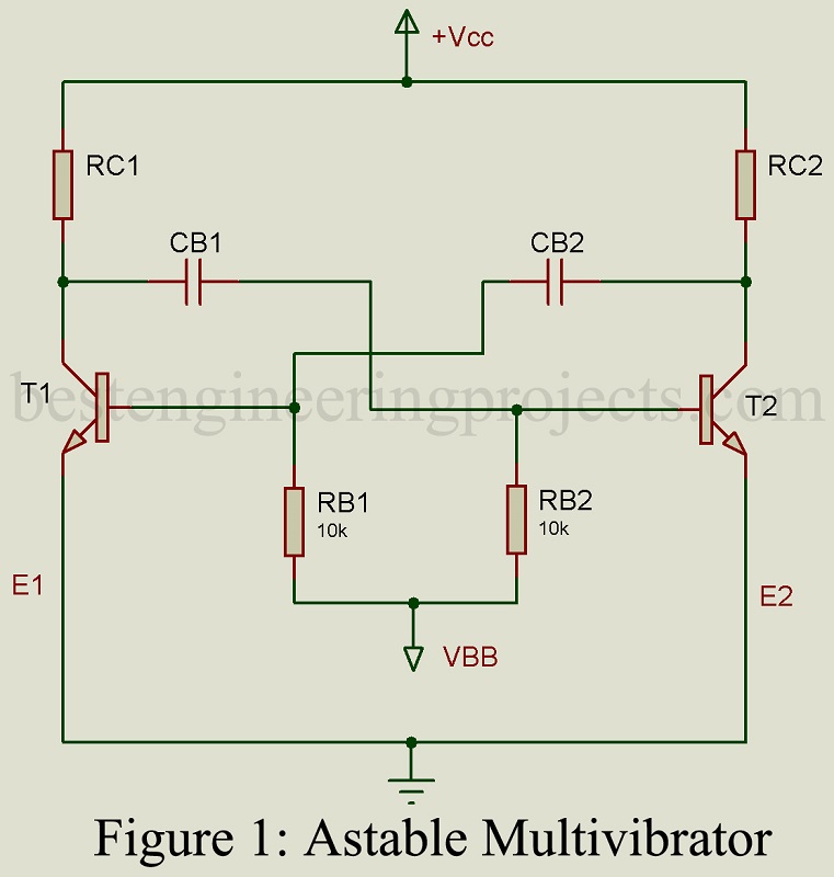
Fig 1 gives the circuit of an astable multivibrator using BJTs while Fig 2 gives the waveforms of collector voltages and base voltages of the two transistors.
Transistor T1 along with collector circuit resistor Rc1 and coupling capacitor Cb1 forms one stage of R-C coupled amplifier. Its output is coupled through capacitor Cb1 to the other R-C coupled amplifier stage formed by transistor T2, collector circuit resistor Rc2 and coupling capacitor Cb2. The output of this second state is coupled through capacitor Cb2 to the input of the first amplifier state. Resistors RB1 and RB2 provide the ON stage base bias currents to the transistors T1 and T2. In a symmetrical astable multivibrator, RB1 = RB2 = RB, Cb1 = Cb2 = Cb, Rc1 = Rc2 = Rc and the two transistors T1 and T2 are identical.
Operation of the Astable Multivibrator Circuit
Starting of Waveform
(i) Let the collector power supply Vcc be suddenly put ON at time t = t1. Then due to slight mismatch, let the collector current Ic1 of transistor T1 be slightly greater than the collector current Ic2 of transistor T2. Then the rate of fall of Vcl is more than that of Vc2.
(ii) For such sudden application of voltage, capacitors act as short circuits and voltages across them cannot change instantaneously. Hence the changes in collector voltages of T1 from the initial value of Vcc to Vc1 (Vc1 < Vcc) will make the base of transistor T2 negative.
(iii) This negative voltage at the base of T2 reduces the conduction current of T2 and increases the collector voltage Vc2 i.e., makes it move towards Vcc.
(iv) This increase in Vc2 gets transferred through capacitor Cb2 to the base of transistor T1 making its base voltage more positive. This increase the collector current of transistor T1.
(v) Increased collector current of T2 will further reduce collector voltage Vcl, make base of T2 more negative and reduce collector current of T2.
(vi) This forms a cumulative action and with loop gain > 1, the whole above sequence of operation occurs instantaneously with the result that transistor T1 goes into saturation while transistor T2 goes into OFF region.
Thus, we find that as soon as this astable multivibrator is switched on, T1 goes ON and T2 goes OFF. Let, this time instant be t = 0.
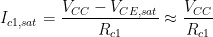
Voltages and Currents of Transistor T1 at time t = 0.
At time t = 0, for large Vcc and large VBB,
 ……(1)
……(1)
 ……(2)
……(2)
 ……(3)
……(3)
 ……(4)
……(4)
Voltages and Currents of Transistor T2 at time t = 0
Collector current of T2 is zero. Hence at t = 0,  …..(5)
Voltage at the base of T2 at time t = 0 can be obtained from the fact that the voltage on capacitor Cb1 is VCC at the instant of switching ON the power supply before the beginning of the regenerative feedback sequence. This implies that the collector terminal of capacitor Cb1 is VCC and the base side voltage is VB2,ON. At the end of the regenerative cycle, the collector side voltage of capacitor Cb1 has fallen from VCC to VCE,sat (almost zero). But the voltage across capacitor Cb1 cannot change instantaneously. Hence the voltage at the base of transistor T2 is given by,
 …..(6)
Circuit Behavior in Quasi-Stable State (0 < t < t1)
Voltage across capacity Cb1 rises from VB2,OFF (t = 0) towards VBB. Charging path is provided by Cb1 and RB2 assuming that  . At any time, instant t, voltage VB2 is given by,
![V_{B2}^{(t)} = V_{BB} + [V_{B2,OFF}(t=0)-V_{BB}] \in \dfrac{-t}{R_{B2}C_{b1}}](https://s0.wp.com/latex.php?latex=V_%7BB2%7D%5E%7B%28t%29%7D+%3D+V_%7BBB%7D+%2B+%5BV_%7BB2%2COFF%7D%28t%3D0%29-V_%7BBB%7D%5D+%5Cin+%5Cdfrac%7B-t%7D%7BR_%7BB2%7DC_%7Bb1%7D%7D&bg=ffffff&fg=000&s=0&c=20201002) …….(7)
…….(7)
Thus the voltage VB2 (t) rises exponentially with time constant RB2.Cb1. However, as soon as VB2 equal VB2,ON at time t1, T2 starts conducting and VB2 (t) remains constant at VB2,ON as shown in Fig 2.
At time t = t1
![V_{B2,ON} = V_{BB} + - VBB [V_{B2,OFF}(t=0)-V_{BB}] \in \dfrac{-t}{R_{B2}C_{b1}}](https://s0.wp.com/latex.php?latex=+V_%7BB2%2CON%7D+%3D+V_%7BBB%7D+%2B+-+VBB+%5BV_%7BB2%2COFF%7D%28t%3D0%29-V_%7BBB%7D%5D+%5Cin+%5Cdfrac%7B-t%7D%7BR_%7BB2%7DC_%7Bb1%7D%7D&bg=ffffff&fg=000&s=0&c=20201002) …….(8)
…….(8)
Solving Equation (6) and (8) simultaneously we get,
![t_1 = R_{B2} \times C_{b1} ln [\dfrac{V_{BB} + (V_{CC}-V_{B2,ON})}{V_{BB}-V_{B2,ON}}]](https://s0.wp.com/latex.php?latex=t_1+%3D+R_%7BB2%7D+%5Ctimes+C_%7Bb1%7D+ln+%5B%5Cdfrac%7BV_%7BBB%7D+%2B+%28V_%7BCC%7D-V_%7BB2%2CON%7D%29%7D%7BV_%7BBB%7D-V_%7BB2%2CON%7D%7D%5D&bg=ffffff&fg=000&s=0&c=20201002) ……(9)
……(9)
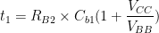
Assuming that VBB >> VB2ON, Equation (9) becomes,
 …….(10)
If VBB = VCC, Equation (10) reduced to,
 …….(11)
Circuit Behavior at time t = t1: At time t=t1, transistor T2 starts conducting since VB2,ON is reached. Collector voltage Vc2 of T2 begins to fall. This fall in Vc2 is coupled through Cb2 to the base of T1 resulting in equal reduction in VB1. This in turn causes reduction in collector current of T1 and increase in collector voltage Vc1 of T1. This increase in Vc1 is coupled to the base of T1 through Cb1 causing increased conduction of T2. This regenerative process continues with the end result that T2 goes into saturation while T1 gets cutoff. This entire process takes place instantaneously at t = t1.
Circuit Behavior during Quasi-Stable State: During this time period, capacitor Cb2 charges from VB2,OFF (t=0) towards VBB, exponentially with time constant RB1.Cb2. At time t = t2, the instantaneous base voltage reaches VB1,ON and transistor T1 goes into conduction.
Time interval (t2 – t1) may be expressed as,
![(t_2-t_1) = R_{B1} \times C_{b2} ln [\dfrac{V_{BB} + (V_{CC}-V_{B1,ON})}{V_{BB}-V_{B1,ON}}]](https://s0.wp.com/latex.php?latex=%28t_2-t_1%29+%3D+R_%7BB1%7D+%5Ctimes+C_%7Bb2%7D+ln+%5B%5Cdfrac%7BV_%7BBB%7D+%2B+%28V_%7BCC%7D-V_%7BB1%2CON%7D%29%7D%7BV_%7BBB%7D-V_%7BB1%2CON%7D%7D%5D+&bg=ffffff&fg=000&s=0&c=20201002) ……(12)
……(12)
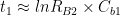
However, VB1,ON is very small compared with VBB. Hence Equation (12) may be put as,
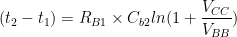 …..(13)
If  …..(14)
Periodic Time: Total time period T is the sum of t1 and (t2-t1).
Thus,  ……(15)
For a symmetrical multivibrator, we have RB1 = RB2 = RB and Cb1 = Cb2 = Cb. Then equation (15) reduces to,
 …..(16)
From Eq. (15) we find that subject to the approximations, periodic time of multivibrator is independent of supply voltage VCC, temperature and junction voltage.
Frequency of astable multivibrator  …..(17)