In this article, you will learn how to Measuring Temperature using PT100 and Arduino. PT100 is a platinum resistance thermometer, which changes its internal resistance according to temperature. In the name PT100, 100 represents ohm i.e. it offers 100-ohm at 00C. Similarly, PT1000 offers 1000-ohms at 00C. PT100 is widely used in industries because of its temperature range.
From the nature of the resistance thermometer, we conclude that tolerance depends upon the range we are using it. When we used to measure temperature nearer to 00C (in both positive and negative), tolerance is minimum. As the difference with 00C increases tolerance also increases. Tolerance is lower at 500C in comparison to 1000C.
Circuit Arrangement and Description of Measuring Temperature using PT100 and Arduino
The circuit for Measuring Temperature using PT100 and Arduino is designed around quad op-amp LM324, Arduino board, display, and a few other electronic components like resistors, capacitors, etc. For a proper description of the circuit, we divided the entire circuit into small sections.

Voltage divider network for PT100:
PT100 is a resistance thermometer i.e. its internal resistor changes according to temperature. A simple voltage divider with a constant voltage source (say 5v), constant resistor, and PT100 is connected as shown in figure 1.
The resistance is changing according to temperature as a result Vout (voltage across PT100) also changes. This changing voltage is depending upon changing resistance.
Note: PT100 is available in different wire connections i.e. 2 wire, 3-wire, and 4-wire. They have only single input and a single output. Let’s say, in this project, we are using 3 wire PT100, one wire is of red color and two-wire are of white color. If you check the continuity between these wires then, two white wires are connected together so just connect both the wire to the ground. If you have PT100 in the 4-wire version then two white wire is shorted together and two red wire is shorted together.
By using the voltage divider formula, we can calculate output voltage. The mathematical formula for voltage divider network

While choosing a fixed resistor (R) we have to consider a few things:
- The value of the resistor (R) must be great enough order to avoid the self-heating problem. If we use low-value resistance more voltage drops across PT100, and as a result, more self-healing. This increases errors.
- The value of R must be low enough in order to avoid the problem of a lower signal-to-noise ratio. If we increase the value of R, the change in magnitude per degree decreases as a result lower signal-to-noise ratio. A large value of R also increases noise which is also responsible for the lower signal-to-noise ratio.
For selecting proper R, we have to do a trade-off between self-heating problems and a better signal-to-noise ratio. Let’s see the consideration for choosing between the value of R.
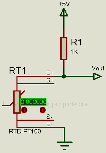
Figure 1: PT100 voltage divider network
Range Selection of Thermometer
Now, let’s suppose we design a thermometer for the 00C to 1500 range. If we consider fixed resistance R = 1K and RTD at 00C = 100-ohm, then output voltage Vout can be calculated as:

Similarly, Vout at 1500C:
According to datasheet of PT100 resistance at 1500C RTD = 157.33
From the above calculation, we have to measure the voltage between 0.4545V to 0.6757V.
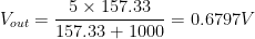
The length of the RTD sensor and its leads is long and might act as an antenna, as a result, it starts to pick up the noise and mixes with temperature voltage. In order to avoid this problem, a capacitor of high value (say 100uF) is connected parallel across the RTD sensor. This capacitor here acts as a low-pass filter and removes almost all noise.
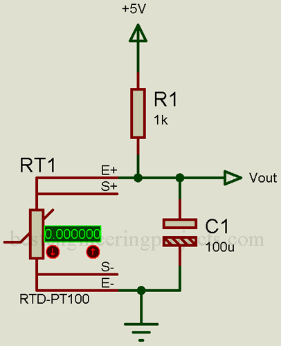
Figure 2: pt100 voltage divider with low pass filter
Voltage follower circuit:
There is two reasons for using a voltage follower circuit:
- To avoid the loading effect.
- Higher input resistance.
The output of PT100 (VOUT) is given to the voltage follower circuit. A voltage follower circuit is basically a unity gain noninverting amplifier. This amplifier circuit is called a voltage follower because the output voltage is equal and in phase with the input. The output of PT100 (VOUT) is connected to the non-inverting terminal where the inverting terminal is connected directly to the output (for unity gain). Check out other applications of operational amplifiers.
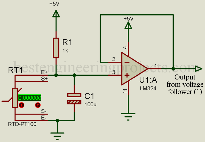
Figure 3: PT100 Voltage Divider Network with Voltage Follower Amplifier
The minimum temperature we are going to measure is 00C. The voltage at this temperature (00C) is 0.45450C. So, we need to subtract this voltage in order to get 0V at 00C. For this purpose, we need a differential amplifier. But before that, we need another constant 0.4545-volt source. For the constant 0.4545 V source, we have designed another voltage follower circuit.
Constant Voltage Source:
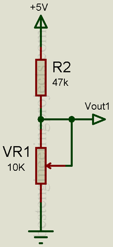
Figure 4: Constant Voltage Divider Network
The constant voltage source is designed using a voltage divider network made from a resistor (R2) and a variable resistor (VR1), adjust the variable resistor so that the output voltage must equal the voltage at the minimum temperature you are going to measure (say 00C, at 00C voltage from PT100 = 0.4545V). Same as above we are using a voltage follower circuit in order to avoid the loading effect. The output from the voltage divider network is connected to the non-inverted terminal where the inverting terminal is connected directly to the output pin.
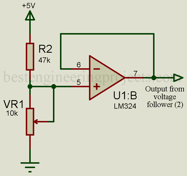
Figure 5: Constant Voltage Divider Network with Voltage Follower Amplifier
Differential amplifier:
A differential amplifier has two input terminals that are both isolated from the ground by the same impedance. The differential amplifier amplifies only the difference in voltage at two input terminals (inverting and non-inverting pins).
The output of PT100 (from the voltage follower amplifier) is given to the non-inverting terminal whereas the output of the fixed voltage source (from the voltage follower amplifier) is given inverting terminal. While designing the differential amplifier we have to calculate gain i.e. up to what input voltage must be amplified.
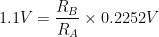
From the derivation of the differential amplifier, the voltage output is given by,
 …..(1)
Where, RB = Feedback Resistor
RA = Input Resistor
V1 = voltage at the inverting terminal
V2 = voltage at the non-inverting terminal
Checkout the derivation and key parameter of the Differential amplifier
Case 1: When the temperature is set to 00C, the output of PT100 is 0.4545V, and the output of the fixed voltage divider is also 0.4545V. The differential amplifier output also becomes zero.
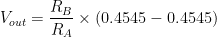

Case 2: when the temperature is at maximum say 1500C voltage output from PT100 = 0.6797V
Differential output, 
Here, gain = RB/RA.
Before calculating the gain of the differential amplifier, let’s clear some doubts.
Selecting the Proper Reference value for Arduino
The default internal ADC reference voltage of Arduino is 5V with 10-bit ADC i.e. it divides input voltage by 210 (1024) division. The resolution of Arduino at 5V = 5/1024 = 4.88mV.
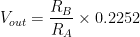
From the above calculation, we found that for the 00C to 1500C temperature range, lower voltage = 0.4545V and higher voltage = 0.6797V.
The voltage difference between lower voltage and higher voltage = 0.6757V-0.4545V = 0.2252V.
Total number of divisions for 0.2252V = 0.2252V/4.88mV = 46.14 i.e. Approximately 47 divisions for 00C to 1500.
Arduino shows 150/47 = 3.250C per division change in voltage i.e. lowest temperature difference Arduino can measure is 3.250C which is not preferable. So, we need an amplifier.
We can use an amplifier at the full range but there are two problems:
- Higher gain: We have to amplify differential input voltage to a high extent (say 5V) as a result we have used the higher value of the feedback resistor.
- External power supply needed: It is difficult to amplify up to supply voltage. According to the datasheet of LM324, maximum amplifier output voltage = supply voltage -1.5V. If we are using 5V from Arduino as the supply voltage then maximum amplified voltage = 5V-1.5V = 3.5V. So, at 5V supply, 1.5V of ADC is wasted. In order to utilize the default 5V reference, we need the external power supply for LM324, which must be greater than 6.5V.
In order to solve the above problem, we are decided to utilize the 1.1V internal ADC of Arduino and this can be selected in the Arduino source code. The resolution of Arduino for 1.1V reference = 1.1/1024 = 1.074mV.
Gain Calculation for differential amplifier
Here, we are using a 1.1V internal reference voltage thus maximum voltage that Arduino can read is 1.1V. So, we have to amplify the maximum differential voltage (say 0.2252V) to 1.1V
Vout = 1.1V
V2-V1 = 0.2252V
Now putting the above value in equation (1)

Therefore, gain = 4.680.
In order to achieve a gain of 4.680, the value of resistor RB must be 4.680 times the value of resistor RA. While choosing the value of resistor RA and RB we have to consider a few things.
- The ratio of resistor RB and RA need to be as close to 4.68 as possible.
- The higher value of the resistor increases noise and decreases power consumption
Here also we have to trade off between noise and power consumption.
| S.N. | Input Resistor (RA) | Feedback Resistor (RB) | Noise | Power Consumption |
| 1 | 1K | 4.68K | Low | High |
| 2 | 10K | 46.8K | Medium | Medium |
| 3 | 100K | 468K | High | Low |
You can use any combination according to your requirement. If we choose 2nd combination (RA = 10K and RB = 46.8K), noise is considerably lower than 3rd combination (RA = 100K and RB = 468K) and power consumption is lower than 1st combination (RA = 1K and RB = 4.68K). So, here we are using 2nd combination.
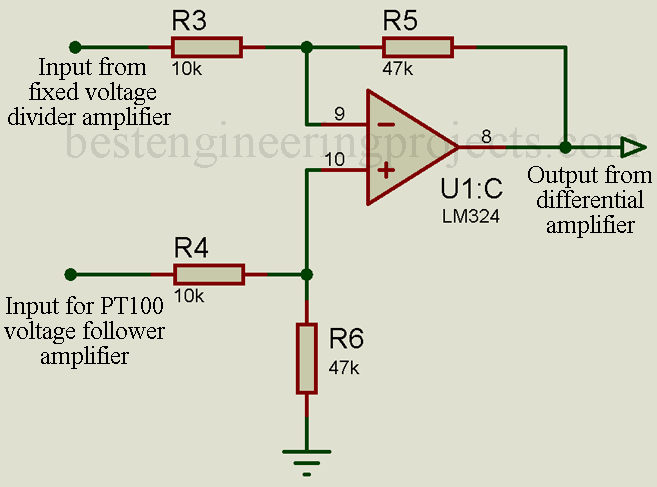
Figure 6: Differential Amplifier for PT100
Arduino Circuit:
The output of the differential amplifier is given to the analog input pin of Arduino. Arduino reads the voltage division, converts it into temperature using the equation, and displays it over LCD. The LCD is connected to Arduino in higher-order data mode i.e. only a higher data bit of LCD (D4 to D7) is connected to Arduino. The output of the differential amplifier is given to analog pin A0. Check out the Tutorial video on how to interface Arduino and 16×2 LCD.
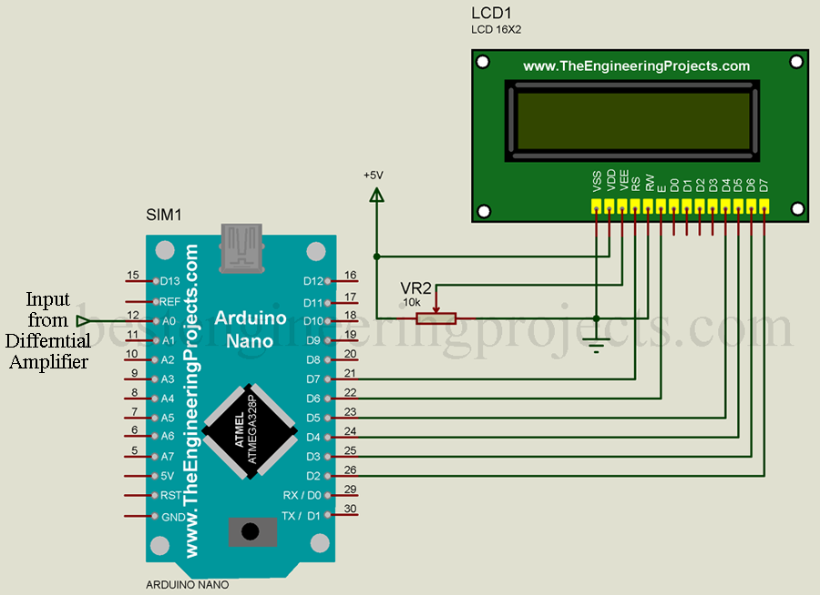
Figure 7: Arduino NANO and Display Interfacing
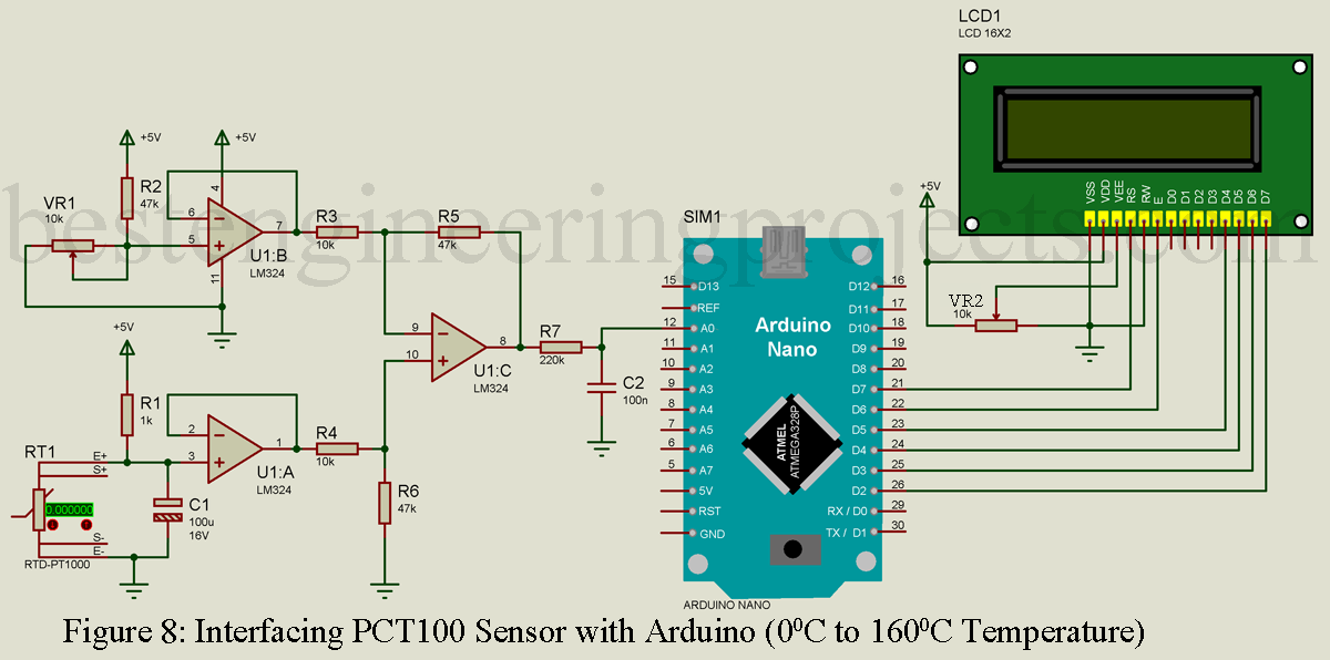
Now, combining all these 7 subsections. Figure 8 shows the complete circuit diagram of Measuring Temperature using PT100 and Arduino.
Component list of Measuring Temperature using PT100 and Arduino
| Resistor (all ¼-watt, ± 5% Carbon) |
| R1 = 1 KΩ
R2, R5, R6 = 47 KΩ R3, R4 = 10 KΩ R7 = 220 KΩ R8 = 330 Ω VR1, VR2 = 10 KΩ |
| Capacitors |
| C1 = 100 µF/16V (Electrolytic Capacitor)
C2 = 100 nF (Ceramic Disc) |
| Semiconductors |
| U1 = LM324 (Quad Op-Amp) |
| Miscellaneous |
| PT100 Temperature sensor
Arduino Nano or equivalent 16×2 Alphanumeric LCD |
Conversion of Voltage to Resistance
Arduino read the voltage from the differential amplifier in division form. The voltage read by Arduino is first converted into resistance using the equation of a straight line i.e. Y = mX + C. Here we have to calculate the value of m (slope) and C (constant). For slope we have to measure voltage and resistance at two different temperatures let’s say at 300C and 1500C.
At temperature T1 (300C)
VT1 = 0.09V
RT1 = 111.2-ohm (According to Datasheet)
At temperature T2 (1500C)
VT2 = 1.1V (As we are using 1.1V internal ADC.)
RT2 = 160-ohm (According to Datasheet)
Formula for slope  ….(2)
….(2)
Let, X1 = 0.09, X2 = 1.1V, Y1 = 160 and Y2 = 111.2. Putting these values in equation (2) we will the value of the slope
Therefore, 
Now, put the value of m (slope) in equation Y = mx+c, in order to find the value of c (constant). At 1500C, RTH = 160-ohm, and Vout = 1.1V.
Now, putting the value Y = 160, x = 1.1 and m = 48.31
C = Y – mx = 160 – 48.31 x 1.1 = 106.852
Also, from datasheet of PT100, value of  = 0.00385
Slope (m) = 48.31
Constant (c) = 106.852
R0 (resistance at 00C) = 100-ohm

These are the value we need in software code.
Software Code for Measuring Temperature using PT100 and Arduino
Software is written in Arduino programming language and compiled using Arduino IDE. While writing software code you have to consider a few things like selecting an internal 1.1V internal ADC. In order to select internal 1.1V internal ADC you have to add syntax in the setup() function.
analogReference(INTERNAL);
Syntax to convert bits into voltage
Volts = (analogRead(Vin)/1023.0)*5.0;
Syntax to convert voltage into resistance
Rx = Volts*slope+C;
Syntax to convert resistance into temperature
temp1= (Rx/R0-1.0)/alpha;
Syntax for calibration
calibration=0.3+(0.005*temp1);
Now let’s see the complete code for Measuring Temperature using PT100 and Arduino
Download the library used in this project.
|
1 2 3 4 5 6 7 8 9 10 11 12 13 14 15 16 17 18 19 20 21 22 23 24 25 26 27 28 29 30 31 32 33 34 35 36 37 38 39 40 41 42 43 44 45 46 47 48 49 50 51 52 53 54 55 56 57 58 59 60 61 62 63 64 65 66 67 68 69 70 71 72 73 74 75 76 77 78 79 80 81 82 83 84 85 86 87 |
#include "Timer.h" #include <LiquidCrystal.h> //Variable decleared float Volts; //voltage read by arduino float tempC; //final temperature in degree celsius after calibration float tempF; //final temperature in degree fahrenhiet after calibration float temp1; //temperatuere before calibration float calibration; //calibration float Rx; //Resistance of PT100 // variables that required to convert voltage into resistance float C = 106.852; //Constant of straight line (Y = mx + C) float slope = 48.31; // Slope of straight line (Y = mx + C) // variables that required to convert resistance into temperatures float R0 = 100.0; //Resistance of minimum temperature to be measured (at 0 degree) float alpha = 0.00385; // value of alpha from datasheet //pin assign ment for sensor int Vin = A0; //pin assignment for LCD const int rs = 7, en = 6, d4 = 5, d5 = 4, d6 = 3, d7 = 2; LiquidCrystal lcd(rs, en, d4, d5, d6, d7); Timer t; // Define Timer object //Setup function void setup() { Serial.begin(9600); // Set Baudrate at 9600 lcd.begin(16, 2); //Start LCD pinMode(Vin,INPUT); // Make Vin (A0) pin as input t.every(100,takeReading); // Take reading of sensor in every 100ms analogReference(INTERNAL); // Taking internal reference 1.1V ADC of arduino } //loop function void loop() { t.update(); // Update Timer } void takeReading(){ // Bits to Voltage Volts = (analogRead(Vin)/1023.0)*1.1; //converting bits of voltage into voltage lcd.setCursor(0, 0); lcd.print("V:"); lcd.setCursor(4,0); lcd.print(Volts); // Converting voltage to resistance Rx = Volts*slope+C; //y=mx+c lcd.setCursor(9,0); lcd.print("R:"); lcd.setCursor(11,0); lcd.print(Rx); // Converting resistnace to temperature temp1= (Rx/R0-1.0)/alpha; // from Rx = R0(1+alpha*X) calibration=0.3+(0.005*temp1); //tolerance for class B PT100 tempC=temp1-calibration; // Final temperature in celsius // conversion of celsius to fehrenheit tempF = tempC*1.8+32; //Final temperature in fehrenheit Serial.println(Volts); Serial.print("V"); Serial.println(Rx); Serial.print("ohm"); lcd.setCursor(0,1); lcd.print(tempC); lcd.setCursor(5,1); lcd.print((char)223); lcd.setCursor(6,1); lcd.print("C"); lcd.setCursor(7,1); lcd.print(tempF); lcd.setCursor(13,1); lcd.setCursor(14,1); lcd.print("F"); Serial.println(tempC); Serial.print(char(176)); Seriallprintln(tempF); Serial.print(char(176)); delay(1000); } |
Making Video of Measuring Temperature using PT100 and Arduino
Check out other top popular Articles :
Clock Signal Generator Circuit
I have completed the circuit part exactly as it is . But facing problem in interfacing
Below are the issues
Error 1: INTERNAL was not disclosed in this scope
Solved : float INTERNAL; I added this and issue is solved
Error 2: SERIAL PORT not connected
Solved : by installing driver from http://www.wch.cn/download/CH341SER_EXE.html
Error 3: error compiling for Arduino Nano
Solution please , the board is
Arduino Nano V3.0 ATMEGA 328P
Please help me to compile and upload this to work … URGENT
INTERNAL is used here for reference voltage, you do not gave to define it as float.
Code is clean and checked, and no need to edit.
Please install latest Arduino IDE form arduino.cc, and then check for driver in device management (Window).
Tried . But unable to download . Showing error : error compiling for Arduino NANO . some times communication timed out .
Might be issue of IDE, please check with example program. and if still show error then please download the new IDE and add arduino nano board manually. There are lots of tutorial over internet.
could you attach the .hex file
Sorry, you can compile and get your own from compiled folder.
Im trying to replace NANO with UNO.
1) Do i need to change anything in code or I can directly use UNO for this project ?
2) the circuit shows 14 pins for 16X2 ALPHANUMERIC display, whereas standard display has 16 pins ( How should it need to be connected)?
3) Terminals of NANO and UNO are slightly different and marked differently . How should be the connection if i replace NANO with UNO? Say A0 will remain same for both, what about Digital out for Display ?
4) How can i turn on a 5vdc computer fan when the measured temperature reaches 50 degree and off when below 40 degree using only arduino output pins and a fan ?
Please help .
Hi Bibuthi, there will be no change in connection and code if you interchange nano with uno. Because it have share same microcontroller i.e.Atmega328.
If you are new to arduino and lcd interfacing then i will recommend you to watch tutorial video on How to interface LCD with arduino
Link: https://youtu.be/NhybrfIrVgE
IF you wish to control the load according to temperature then i will recommend you to go through these article
Arduino Based Temperature Control Fan.
This device can control speed of fan according to temperature.
Thankyou.
Can i use this code and circuit for UNO ? Any changes required in code or hardware circuit and connections ?
How do i connect a 16 pin display ( circuit shows 14 pin) ?
How to turn on a 5vdc fan with this circuit when temp reach 50 degree and off when temp reach 40 deg ? Using code and fan alone ?
New to Arduino and IDE. Please explain
Thank for the fast replay . No I don’t need control of fan. Just turn on fan when display read 50 degree and off fan when temperature below 40 degree . Can I do this with only a 5vdc fan and code ? Please help
For fan you need switching circuit, because maximum current you can withdraw from arduino I/O pin 40mA.
Dear Best Engineering projects,
I managed to successfully do this project . Could you assist to modify this project with below requirements
1. Serial Port monitor is just showing Temperature without any units (Only degrees, no volt, resistance or Fahrenheit. How do you modify the code to show identical to LCD display.
2. What should be added to the code to energies pin 13 of Arduino uno so that the pin13 LED (Inbuilt LED) will glow when temperature is greater than 50 degrees.
I really appreciate your prompt support .
Once again thanks for your project . Would really recommend .
Hi, i had modified the code according to your requirement in point 1.
For point 2.
in void setup() function add this line of code
pinMode(LED_BUILTIN, OUTPUT);
and in void takeReading()function just above add these line
if(tempC > 50)
{
digitalWrite(LED_BUILTIN, HIGH);
}
else {
digitalWrite(LED_BUILTIN, LOW);
}
Thankyou
Could you assist to modify this project with below requirements,
1. Serial Port monitor is just showing Temperature without any units (Only degrees, no volt, resistance or Fahrenheit. How do you modify the code to make serial monitor also show identical to LCD display.
2. What should be added to the code to energies pin 13 of Arduino uno so that the pin13 LED (Inbuilt LED) will glow when temperature is greater than 50 degrees.
I really appreciate your prompt support .
Once again thanks for your project . Would really recommend you.
I am trying to develop the same system but my requirement is to get value from 0 to 300 deg C can i use the same feedback resistance and slop, constant. To get this much range.
Feedback resistor is same but slope and constant is changed because voltage and resistance at 300 degree is different from voltage and resistance at 150 degree (Refer to “Conversion of Voltage to Resistance” heading). For this value please prefer datasheet of PT100.
can i use the same logic, circuit and code with 8051 which has a internal ADC of 12 Bit.
Hi,
Can i use the same logic, circuit and code for interfacing PT100 with 8051 which has internal 12 Bit ADC
Circuit and logic will be almost same but code and pin connection of 8051 and amplifier section will be different.
can you please provide me circuit or any details of how can i use it with 8051.
what changes have to be done on code and amplifier section.
Hi gaurav,
Sorry, we cannot provide you complete project buy surely help you to build your own.
Thanks
Hi,
Thanks, how can we proceed.
My Mail Address is: [email protected]
Please send me a test message.
At temperature 0 degree Celsius,
what will be the value of VT1 ??
At 0 degree Celsius, resistance of PT100 is zero. Thus voltage also become zero.
@ 0 degree Celsius VT1 = 0V.
Hi.
What is the lowest temperature difference that this circuit reads!?
What happens if you use a 16bit or 32bit Adc arduino?
Hi, the lowest temperature difference of this circuit is 0.146 degree Celsius.
If you use higher bit ADC then temperature difference will be further decreases.
in case of 16bit ADC and 1.1V reference the temperature difference that circuit can read = 0.002 degree celsius.
Thanks for a well built and explained project. I have been able to use this base to create a thermally actuated relay for temperature control on a smoker.
One thing bothers me, though. There’s no explanation on why the output from the last opamp is passed through R7 (220kohm) and in parallel with the capacitor.
I guess the resistor is to reduce current and the capacitor is to reduce noise, but are they necessary and what affects the resistance and capacitance?
There’s no explanation in the article, but I found in the video that it was mentioned that they are passed through the resistor and capacitor. Additionally there was mention of the capacitor acting as a low pass filter.
There was, however, no details on why the value of the resistor is 220kohm or why it has been added in the first place.
Please help me understand this.
library for timer.h cannot used
Would it be possible to program Callendar-Van-Dusen values into this?
Yes, you can program by assigning all the required value.
plz, i have problem with Timer t. it doesn’t accept it
I also have a problem with timer t
Could you clarify which part you need elaboration on?