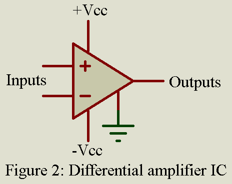
Differential amplifier have two input terminals that are both isolated from ground by the same impedance. This amplifier is basically used in industrial and instrumentation purpose because this type of amplifier are better able to reject common-mode (noise) voltage then single-input circuits such as inverting and non-inverting amplifier. Basically, a Class A voltage amplifier, the differential amplifier amplifies only the difference in voltage between its two terminals. Signals that appears at both terminals are not amplified, allowing the differential amplifier to pick up weak signals in the presence of strong magnetic and electric interference. This ability to reject signals that are common to both input terminals is expressed in the common-mode rejection ratio.
We will analyze the circuit of differential amplifier by driving gain and its input resistance.
At first let derive voltage gain
Voltage gain of differential amplifier:
From the above circuit we can see that there are two input V1 and V2. In order to find the relation between input and output we have to use superposition theorem. If we are using superposition theorem, we have to assume all other voltage source zero. Let’s assume V2 = 0, then the configuration become inverting amplifier, hence the output is only available due to V1.
Output due to V1 ….(1)
Similarly, when V1 = 0V, the configuration become non-inverting amplifier with voltage divider network composed of resistor R2 and R3 at non-inverting input as shown in circuit diagram. Therefore, voltage at non-inverting terminal become,
And the output due to V1 become
Now the equation of output become
If we consider R1 = R2 and RF = R3, the equation becomes
….(2)
Thus, from the above equation (1) and (2), the total output voltage is
Or, the voltage gain
From the above equation we can say that the expression for voltage gain of differential amplifier is same as voltage gain of inverting amplifier.
Input Resistance:
The input resistance of the differential amplifier can be determined by looking into one input terminal with other grounded. Let say, V2=0, the circuit of figure 1 become inverting amplifier the input resistance of which is,
….(3)
Similarly, when we make V1 = 0, the differential amplifier shown in figure 1 becomes a non-inverting amplifier whose resistance become
…(4)
From above equations (3) and (4) we can say that the resistance seen from single source i.e. from V1 and V2 is not the same. In order to perform properly, the value of both R1 and (R2 + R3) must be made much larger than the source resistance so that the loading of the signal sources does not occur.
Key parameters of Differential Amplifier IC
- Common-mode rejection ratio (CMRR): A measure of the differential amplifier’s input characteristic. CMRRs of 100 dB and up are readily available.
- Input common-mode range: The maximum positive and negative voltage that will be rejected by the CMRR at the input.
- Differential voltage gain: Indicates the amplification of the differential input voltage.
- Bandwidth: indicates the frequency range in a conventional manner.
- Input Resistance: The impedance between the two differential input terminals.
- Input offset voltage: Usually measured in millivolts, it indicates the amount of unbalance between the input terminals.
Applications of Differential amplifier
Widely used in all types of amplifiers, in a variety of instruments in industry, scientific laboratories, and medical applications where small signals must be amplified in the presence of external interference.
Comments
Differential amplifiers are available with differential output or with signal output. In many models the gain is selectable by strapping external terminals or connecting outboard resistors. Very high impedance inputs are provided by FET technology, combined with conventional bipolar transistors.

