This article shows you how to design a high-power motor driver for Bluetooth Controlled Robot using Arduino and relay. Previously, we had posted an Arduino-based Bluetooth-controlled car designed around L293D motor driver IC. There is some limitation of the L293D motor driver IC i.e. output current is limited to 600mA. What if you wish to drive a DC motor that consumes more than 1A? Let’s say 5A. For this, you need a more powerful circuit that delivers appropriate power to the motor. So, here you will learn how to make a cheap 10A @ 28V DC motor driver circuit using Relay. The best engineering projects team is thankful to kantibir robotics for help and support throughout the projects
Features of Bluetooth Controlled Robot using Arduino:
- Wide supply voltage range for the motor.
- Bluetooth controlled i.e. you can control the motor using your smartphone.
- MOSFET is used instead of a transistor for fast and flawlessly switching.
- Individual Diode across each relay for inductive transient suppression.
- Dedicated Snubber circuit for individual motor.
- High-noise-immunity inputs with separate input-logic supply.
- Dedicated Led across each relay for proper indication of relay functioning.
- Single input power supply.
Components required
1x Arduino Nano
1 x HC-06 Bluetooth Module
4 x IRFZ44N MOSFET
4 x SC5-S-DC6V Relay
4 x 1N4007 Diode
4 x 220-ohm Resistor
4 x 5.6 k-ohm Resistor
2 x 5-ohm 5-Watt Wire wound resistor
4 x 0.1uF Ceramic Capacitor
2 x 0.01uF Ceramic Capacitor
1 x LM7806 6V Series Fixed Voltage Regulator
1 x LM7809 9V Series Fixed Voltage Regulator
4 x 5mm any color LED
2 x motor as required.
Circuit Description of Bluetooth Controlled Robot using Arduino
The circuit diagram of the Robot controller is shown in figure 1, it is built around Arduino nano, a Bluetooth module, and four relays with its switching circuit. Bluetooth module communicates with Arduino in serial communication mode thus TXD pin of HC-06 Bluetooth module is connected to RX (D0) of Arduino where RXD is connected to TX (D1) pin of Arduino nano as shown in the circuit diagram. Vcc of Bluetooth is connected to +5V and GND pin is connected to GND pin of Arduino nano.

Four digital pins of Arduino nano are used to trigger the gate of MOSFET Q1 through Q4 as shown in the circuit diagram. These four MOSFETs drive four Relay. Here we are not controlling the speed of the motor but only switching it on and off, thus no need to use the PWM pin of Arduino nano. Four resistors of 5.6k-ohm are connected to the gate to the ground of each MOSFET to avoid false triggering. The source pin of each MOSFET is grounded where the drain pin of each MOSFET is connected to one end of each relay coil as shown in the circuit diagram. Another end of each coil is connected to a +6V power supply. A LED with a current limiting resistor is connected across each relay coil for indicating whether the relay is active or not i.e. glowing LED represents the respective relay is active. Please check out How to make a relay switching circuit.
The positive terminal of the battery is connected to the NC (Normally Closed) terminal of each relay (RL1 to RL4) whereas the negative terminal of the battery is connected NO (Normally Open) terminal of each relay. The common terminal of relays is connected to the motor. The common terminal of relay RL1 is connected to one end of motor M1 whereas the common terminal of relay RL2 is connected to another end of motor M1. Similarly, motor M2 is connected to the common terminal of relay RL3 and RL4. A snubber circuit made from a capacitor and resistor is added across both the motor to protect a circuit from voltage spikes caused by the circuit’s inductance (motor).
A snubber circuit is an energy-absorbing circuit that generates across inductive loads. Here in this circuit we are using the most common snubber circuit i.e. made from a resistor and capacitor connected in series. When we power cut across inductive load it generates voltage spike, this spike charges the capacitor where resistor discharges it and convert this voltage into heat.
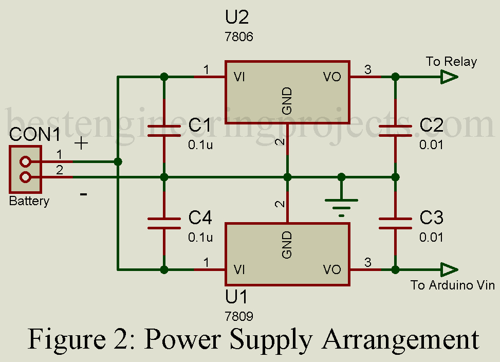
Power supply circuit. The power supply circuit is designed around two series voltage regulator IC. LM7809 (IC1) is used here to power Arduino whereas LM7806 (IC2) is used to power the relay. Vin pin of both of these regulators is connected to the battery positive terminal whereas the GND pin is connected to the negative terminal of the battery. VO pin (pin 3) of LM7809 is connected to the Vin pin of Arduino nano and the Vo pin (pin 3) of LM7806 is connected to one end of each coil of the relay.
Working on Bluetooth Controlled Robot using Arduino
Initially, all the relay is de-energized because no command is coming from the Arduino board. At de-energized conditions, all the common pin of the relay is connected to the NO pin of the relay. From the circuit diagram, it is clear that at this state both the terminal of the motor is at the same potential so no current follow as a result motor does not rotate. When we energize relay RL1 and de-energize the relay RL2 motor start to rotate in a clockwise direction. Similarly, when we energized relay RL2 and de-energized relay RL1 motor start to rotate in the anti-clockwise direction. If we energized both the relay the motor stopped because of the same potential at both terminals of the motor. Similarly, motor M2 operates.
| Table 1: Operation of Motor | ||||||
| S.N. | RL1 | RL2 | RL3 | RL4 | M1 | M2 |
| 1. | OFF | OFF | OFF | OFF | OFF | OFF |
| 2. | ON | OFF | OFF | OFF | Clockwise | OFF |
| 3. | ON | ON | OFF | OFF | OFF | OFF |
| 4. | OFF | ON | OFF | OFF | Anti-clockwise | OFF |
| 5. | OFF | OFF | ON | OFF | OFF | Clockwise |
| 6. | OFF | OFF | ON | ON | OFF | OFF |
| 7. | OFF | OFF | OFF | ON | OFF | Anti-clockwise |
| 8. | ON | OFF | ON | OFF | Clockwise | Clockwise |
| 9. | OFF | ON | OFF | ON | Anti-clockwise | Anti-Clockwise |
| 10. | ON | OFF | OFF | ON | Clockwise | Anti-clockwise |
| 11. | OFF | ON | ON | OFF | Anti-clockwise | Clockwise |
| 12. | ON | ON | ON | ON | OFF | OFF |
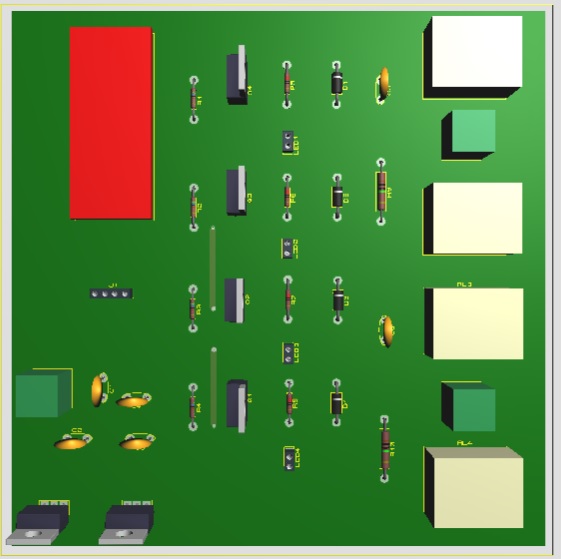
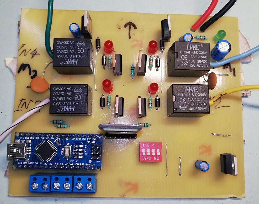
Figure 3: PCB Prototype of Bluetooth Controlled Robot using Arduino
PCB Design: The PCB diagram of Bluetooth Controlled Robot using Arduino is designed using proteus 8.1. Solder side PCB and component side PCB is shown in the figure below. Download the PCB in PDF format from the link below.
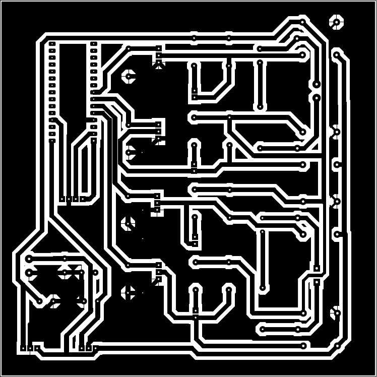
Figure 4: Solder Side PCB Diagram
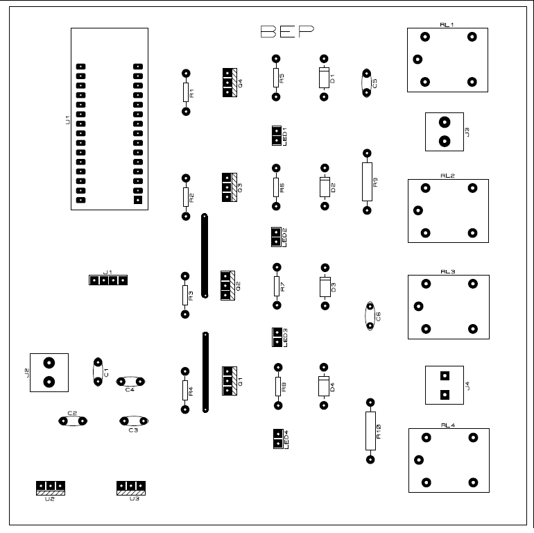
Figure 5: Component Side PCB Diagram
Note: For the android app and its configuration please do refer to this tutorial: Arduino Based Bluetooth Car
Software Code: Software code is written in Arduino programming language and is compiled using Arduino IDE. Code is simple. We are using serial communication with a Bluetooth module. Bluetooth receives data from the smartphone and sends it to Arduino nano. Arduino nano compares the string and operates according to the data available.
|
1 2 3 4 5 6 7 8 9 10 11 12 13 14 15 16 17 18 19 20 21 22 23 24 25 26 27 28 29 30 31 32 33 34 35 36 37 38 39 40 41 42 43 44 45 46 47 48 49 50 51 52 53 54 55 56 57 58 59 60 61 62 63 64 65 66 67 68 69 70 71 72 73 74 75 76 77 78 79 80 81 82 83 84 85 |
#define RelayLeft 2 #define RelayRight 3 #define RelayForward 4 #define RelayBack 5 char Available = 'S'; char ReturnVal; char GetVal; void setup() { Serial.begin(9600); pinMode(RelayLeft, OUTPUT); pinMode(RelayRight, OUTPUT); pinMode(RelayForward, OUTPUT); pinMode(RelayBack, OUTPUT); } void loop() { GetVal = check(); while (GetVal == 'F') //Fordware { digitalWrite(RelayLeft,HIGH); digitalWrite(RelayRight,LOW); digitalWrite(RelayForward,LOW); digitalWrite(RelayBack,HIGH); delay(10); GetVal = check(); } while (GetVal == 'B') //Backward { digitalWrite(RelayLeft,LOW); digitalWrite(RelayRight,HIGH); digitalWrite(RelayForward,HIGH); digitalWrite(RelayBack,LOW); delay(10); GetVal = check(); } while (GetVal == 'R') //Right { digitalWrite(RelayLeft,LOW); digitalWrite(RelayRight,HIGH); digitalWrite(RelayForward,LOW); digitalWrite(RelayBack,HIGH); delay(10); GetVal = check(); } while (GetVal == 'L') //Left { digitalWrite(RelayLeft,HIGH); digitalWrite(RelayRight,LOW); digitalWrite(RelayForward,HIGH); digitalWrite(RelayBack,LOW); delay(10); GetVal = check(); } } int check() { if (Serial.available() > 0) { Available = Serial.read(); if (Available == 'F') { ReturnVal = 'F'; } else if (Available == 'B') { ReturnVal = 'B'; } else if (Available == 'L') { ReturnVal = 'L'; } else if (Available == 'R') { ReturnVal = 'R'; } } return ReturnVal; } |