The P10 LED display is a single color (red, blue, and yellow), high brightness, lower power consumption, and long lifetime display module designed for semi-outdoor use. One display module we are using contains 16×32 = 512 LEDs. In the tutorial “Interfacing P10 LED Display with Arduino“, you will learn:
- How to interface P10 Led display with Arduino
- How to select text font and size of the character
- How to display static character and running character.
Introduction to P10 Display
P10 display is a dot-matrix LED display. Dot-matrix Led means a group of LEDs set as a two-dimensional array also called a 2D matrix array. Here each dot represents circular lenses in front of LEDs. Dot-matrix Display or Running Text Display is often used in shops to advertise their products. The module we are using contains a total of 512 no. of LEDs. They can display different types of characters, symbols, or messages (e.g. “Hello! World”). We can connect multiple numbers of these types of displays in matrix format (i.e. ROW and COLUMN arrangement).
Pin Description of P10 Display Module
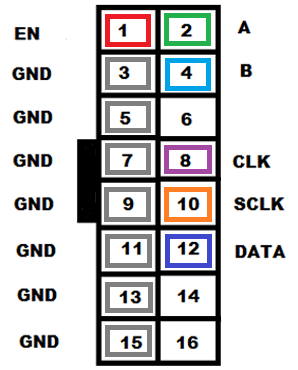
Figure 1: P10 Module Pinout
- Enable: This pin is used to control the brightness of the LED panel, by giving a PWM pulse to it.
- A, B: These are called multiplex select pins. They take digital input to select any multiplex rows
- Shift clock (CLK), Store clock (SCLK): These are the regular shift register control pins
- Data: This pin is for data input in PWM form.
Features of the P10 Display module:
- ¼ duty scan type [one out of four LEDs on the module are driven by IC at one time]
- Brightness:3500nits to 4500nits
- Max Power Consumption: 20W
- DC 5V Voltage Input
- IP65 Waterproof
- High contrast ratio and viewing angle
- 1W pixel configuration
Specification of the P10 Display Module:
- Input voltage: 5V
- Max current input: 4A
- Average power consumption: 8W-10W
- Colour: Red
- Pixel Pitch: 10mm
- Led Pixel Size: 32X16 = 512
Interfacing P10 LED Display with Arduino:
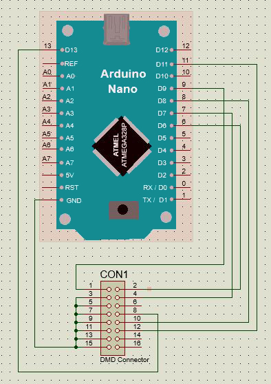
Figure 2: Wiring Diagram of interfacing P10 display with Arduino
Connect the P10 LED Display with Arduino according to the pin configuration shown in the above figure. Here P10 Display module consists of 16 pin connectors (DMD Pins). So connect DMD-pins 3, 5, 7, 9, 11, 13 & 15, to a ground pin of the Arduino board (as shown in the figure). Then connect DMD-Pin 1 (EN pin) to D9 (PWM pin of nano). Similarly, connect DMD-Pin 2 (A) to D6 (PWM pin of nano) and DMD-Pin 4 (B) to D7(nano). Lastly connect DMD-Pins 8,10 &12 to nano pins D13, D8 & D11 for CLK, SCLK, and DATA inputs respectively. DMD-Pins 6,14 &16 are kept open, as shown in Figure 2.
Components required for Interfacing P10 LED Display with Arduino:
- Jumper wires
- Arduino Nano
- P10 display
- 5V @ 4A DC supply
Introduction to FONT used in the P10 Display module:
While displaying in P10 we can choose from multiple libraries according to our needs. For this article, we only use 3 font types out of many, which are:- “SystemFont5x7”, “Arial_black_16” and “Arial14”.
- The font <SystemFont5x7>, lets you display characters with a simple design and each character consumes 5-row LEDs & 7-column LEDs (i.e. 35 LEDs; Font width=5; Font height=7). This font type allows you to display a series of characters in two rows (i.e.over the whole 32X16 P10 display module).
- Similarly <Arial_black_16>, lets you display characters with the Arial_black style which is part of the Arial font family with a larger character set. In this font type, each character consumes 10 row LEDs by 16 column LEDs (i.e. 160 LEDs; Font width=10; Font height=16). This font type allows you to display only a single row worth of characters since the P10 module consists of only 16 LEDs vertically.
- Lastly, the font <Arial14> displays characters in the most widely known Arial Font style. This style is a tiny bit smaller in size than the <Arial_black_16>. It consumes 10 row LEDs by 14 column LEDs (i.e. 140 LEDs; Font width=10; Font height=14). Choosing this font type only allows a single row of characters similar to the Arial_black_16 font style.
How to select Text Font on P10 display:
First, you need the libraries required to operate and communicate with the display module. The stable ones are <DMD.h> and <SPI.h> which ensure smooth coordination between the Arduino controller and the display module. Another library called <TimerOne.h> is needed provides interrupts.
Now, you need to include their libraries to use the font style “SystemFont5x7” or any other font style while displaying characters. To use the SystemFont5x7 font style you need to download the SystemFont5x7.h library file. Similarly, for “Arial_black_16” and “Arial14”, you need to download the Arial_black_16.h and Arial14.h library files.
Library link: DMD library includes DMD.h, SystemFont5x7.h, Arial_black_16.h, Arial14.h
Software Code of Interfacing P10 LED Display with Arduino:
Before displaying in P10 you need to know, how many characters can a module fit at once? (depending on font style). Also while passing strings from Arduino to P10, some garbage value might also be included. So to avoid any unnecessary hassle, you can convert the strings you want to display into an array of characters. For this, you define a char array “b[8]” and string variable “str” as shown in below sample code. This step will make sure that all characters are displayed without errors and with appropriate length.
|
1 2 3 4 5 6 7 8 9 10 11 12 13 14 15 16 17 18 19 20 21 22 23 24 25 26 27 28 29 30 31 32 33 34 35 36 37 38 39 40 41 42 43 44 45 46 47 48 49 50 51 52 53 54 55 56 57 58 59 60 61 |
#include <SPI.h> #include <DMD.h> #include <TimerOne.h> #include "SystemFont5x7.h" #include "Arial_black_16.h" #include "Arial14.h" #define DISPLAYS_ACROSS 1 #define DISPLAYS_DOWN 1 String str; char b[8]; DMD dmd(DISPLAYS_ACROSS, DISPLAYS_DOWN); void ScanDMD(){ dmd.scanDisplayBySPI(); } void setup() { Serial.begin(9600); Timer1.initialize(5000); Timer1.attachInterrupt(ScanDMD); dmd.clearScreen(true); } void loop() { int slen = 0; dmd.clearScreen( true ); /*--------------------------------------- Display using SystemFont -------------------------------------*/ dmd.selectFont(SystemFont5x7); str="HELLO"; slen = str.length()+1; str.toCharArray(b,slen); dmd.drawString(1,0,b,slen,GRAPHICS_NORMAL); str="WORLD"; slen= str.length()+1; str.toCharArray(b,slen); dmd.drawString(1,8,b,slen,GRAPHICS_NORMAL); delay(4000); dmd.clearScreen( true ); delay(2000); /*--------------------------------- Display using Arial_black_16 -------------------------------------*/ dmd.selectFont(Arial_Black_16); str="BEP"; slen = str.length()+1; str.toCharArray(b,slen); dmd.drawString(2,1,b,slen,GRAPHICS_NORMAL); delay(4000); dmd.clearScreen( true ); delay(2000); /*---------------------------------- Display using Arial14 -------------------------------------------- */ dmd.selectFont(Arial_14); str="BEP!"; slen = str.length()+1; str.toCharArray(b,slen); dmd.drawString(4,1,b,slen,GRAPHICS_NORMAL); delay(4000); dmd.clearScreen( true ); delay(2000); } |
The output of the Program:

Figure 3: “HELLO WORLD” using <SystemFont5x7.h>
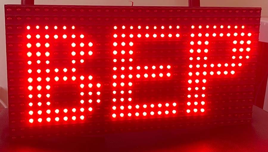
Figure 4: “BEP” using <Arial_black_16.h>
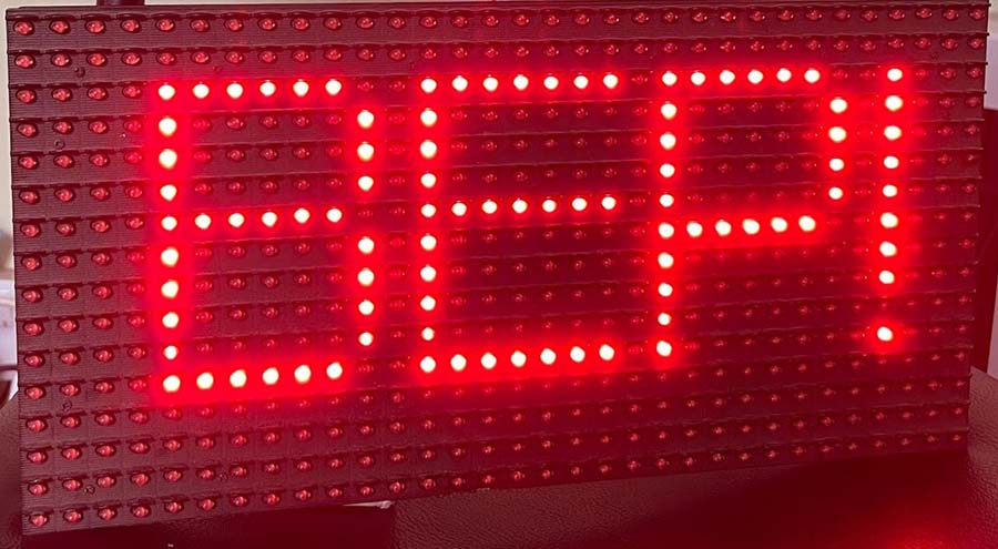
Figure 5: “BEP!” using <Arial14.h>
How to display Characters (Static and Running)
After completing the hardware interface between P10 and Arduino, we will be creating a program to display a static and running message in the P10 display. Below is the stepwise explanation of the program code.
- Include necessary libraries:
Some important libraries such as <SPI.h> for Serial communication, <DMD.h> for P10 display operations and <TimerOne.h> for interrupts tasks need to be included in the program. Include the display font library <Arial_black_16.h> and <SystemFont5x7.h> for large and small sized text displays.
- Define necessary variables:
Initialize a char type array “b[]” and string variable “str” as shown in code. Then define the number of modules we have to display_across and display_down. In our case we are using only one module, so Display_accross and Display_down value will be 1. Lastly, initialize an object of the DMD class to carry out display operations with parameters: “Display_accross and Display_down”.
- Define Scan_module() function:
scan_module() function will check for any incoming data from the Arduino side through the SPI Terminals. If yes, then it will trigger an interrupt pin for certain events.
- Initialize the Setup function:
Inside setup(), initialize the timer and attach the interrupt to the function scan_module() with 5000-microsecond intervals to initiate the ScanDMD call. Also, a time period longer than 5000 (5ms) can cause a flicker in the display. Here dmd.clearScreen(true) is used to set all pixels off initially to clear the display board.
- Display a simple “HELLO WORLD” message (Static or Fixed Characters):
Then finally we utilize the string variable “str” to store some string and convert it to byte form using the “.toCharArray()” function and store it in a byte type array “b[8]”. Then select a font using “.selectFont()” and display the contents using “.drawString()” as shown above. Lastly, clear the screen after a 1-sec delay using “.clearScreen()”.
Code for Static Character
|
1 2 3 4 5 6 7 8 9 10 11 12 13 14 15 16 17 18 19 20 21 22 23 24 25 26 27 28 29 30 31 32 33 34 35 36 37 38 39 |
#include <SPI.h> #include <DMD.h> #include <TimerOne.h> #include "SystemFont5x7.h" #include "Arial_black_16.h" #include "Arial14.h" char b[8]; String str; #define DISPLAYS_ACROSS 1 #define DISPLAYS_DOWN 1 DMD dmd(DISPLAYS_ACROSS, DISPLAYS_DOWN); void ScanDMD(){ dmd.scanDisplayBySPI(); } void setup() { Serial.begin(9600); Timer1.initialize(5000); Timer1.attachInterrupt(ScanDMD); dmd.clearScreen(true); } void loop() { int slen = 0; dmd.selectFont(SystemFont5x7); str="HELLO"; slen = str.length()+1; str.toCharArray(b,slen); dmd.drawString(0,0,b,slen,GRAPHICS_NORMAL); str="WORLD"; slen= str.length()+1; str.toCharArray(b,slen); dmd.drawString(0,8,b,slen,GRAPHICS_NORMAL); //(x, y, value, length,type) delay(4000); dmd.clearScreen( true ); } |
Displaying Running or Sliding character in P10 Display:
All these declaring, defining, and “void setup()” part of the code for scrolling action is identical to the above static ones. So, to display a sliding character only the code in “void loop()” needs some changes. Here we use two new function of DMD library called .drawMarquee() and .stepMarquee(). Also, millis() is used to determine the speed of scrolling.
The drawMarquee function starts drawing the scrolling text onto the DMD. The text is read from an array of char “b[8]”. The drawMarquee function is also initialized with the length of the text message, and with the position from where the message is to appear. In this example, scrolling will start from the right side of the DMD, (i.e. the LED at the 31st column and 1st row). Whereas, the function stepMarquee is responsible for updating the texts. Its parameters control the direction of the scroll. With (-1,0), the text will move 1 – LED to the left and 0 – LED vertically. But, If you want to move the text toward the right, use (1,0).
Code for Running Character
|
1 2 3 4 5 6 7 8 9 10 11 12 13 14 15 16 17 18 19 20 21 22 23 24 25 26 27 28 29 30 31 32 33 34 35 36 37 38 39 40 41 42 43 |
#include <SPI.h> #include <DMD.h> #include <TimerOne.h> #include "SystemFont5x7.h" #include "Arial_black_16.h" #include "Arial14.h" char b[8]; String str; #define DISPLAYS_ACROSS 1 #define DISPLAYS_DOWN 1 DMD dmd(DISPLAYS_ACROSS, DISPLAYS_DOWN); void ScanDMD(){ dmd.scanDisplayBySPI(); } void setup() { Serial.begin(9600); Timer1.initialize(5000); Timer1.attachInterrupt(ScanDMD); dmd.clearScreen(true); } void loop() { int slen=0; dmd.selectFont(Arial_Black_16); str = "BestEngineeringProject.com"; slen = str.length()+1; str.toCharArray(b, slen ); dmd.drawMarquee( b, slen, (32*DISPLAYS_ACROSS)-1 ,1); unsigned long timing = millis(); boolean flag = false; while (!flag) { if ((timing + 70) < millis()) { flag = dmd.stepMarquee(-1, 0); timing = millis(); } } } |