In this article we will discuss about basic radar, and basic radar block diagram. Lets start with basic description of RADAR.
What is RADAR?
The first practical use of waveguides occurred with the development of radar during World War II. The high powers and high frequencies involved in these systems are much more efficiently carried by waveguides than by transmission lines. The word radar is an acronym formed from the words radio detection and ranging. Radar is a means of employing radio waves to detect and locate objects such as aircraft, ships, and land masses. Location of an object is accomplished by determining the distance and direction from the radar equipment to the object. The process of locating objects requires, in general, the measurement of three coordinates: range, angle of azimuth (horizontal direction), and angle of elevation.
A radar set consists fundamentally of a transmitter and a receiver. When the transmitted signal strikes an object (target) some of the energy is sent back as a reflected signal. The small-beam width transmit/receive antenna collects a portion of the returning energy (called the echo signal) and sends it to the receiver. The receiver detects and amplifies the echo signal, which is then used to determine object location.
Military use of radar includes surveillance and tracking of air, sea, land, and space targets from air, sea, land, and space platforms. It is also used for navigation, including aircraft terrain avoidance and terrain following. Many techniques and applications of radar developed for the military are now found in civilian equipment. These include weather observation, geological search techniques, and air traffic control units, to name just a few. All large ships at sea carry one or more radars for collision avoidance and navigation. In space, radars are used for spacecraft rendezvous, docking, and landing, as well as for remote sensing of the earth’s environment and planetary exploration.
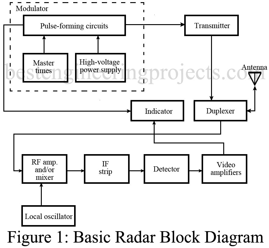
Basic Radar Block Diagram
A basic radar block diagram is shown in Fig. 1. The pulse repetition frequency is controlled by the timer (also called trigger generator or synchronizer) in the modulator block. The pulse-forming circuits in the modulator are triggered by the timer and generate high-voltage pulses of rectangular shape and short duration. These pulses are used as the supply voltage for the transmitter and, in effect, turn it on and off. The modulator, therefore, determines the pulse width of the system. The transmitter generates the high-frequency, high-power RF carrier and determines the carrier frequency. The duplexer is an electronic switch that allows the use of a common antenna for both transmitting and receiving. It prevents the strong transmitted signal from being received by the sensitive receiver.
The receiver section is basically a conventional super-heterodyne receiver. In older radars no RF amplifier is found, due to noise problems with the RF amplifiers of that era.
waveguides are used now with conjunction magnetrons to
accelerate electrons which after impact with ametal plate produce X-Ray. In cancer therapy, they are used.
First time the waveguide was performed by Mulard electronics
Crawley.