The microphone is a transducer that converts sound signals to electrical signals. The output electrical signals are very weak ranging from 1 millivolt to 100 millivolts. Microcontrollers like Atmega328 (Arduino), PIC, STM, etc. cannot detect this signal effectively. Thus, we need an amplifier section. The project posted here is of dual microphone preamplifier circuit which amplifies lower electric output signals of the microphone and makes it suitable for microcontroller input. Checkout other microphone amplifiers and preamplifier circuits posted in bestengineeringprojects.com
- Dynamic Microphone Preamplifier Circuit
- Microphone Amplifier using Op-amp 741 IC
- Listening Bug Circuit using Op-Amp LM386
- DIY Hearing Aid Circuit using 555 IC
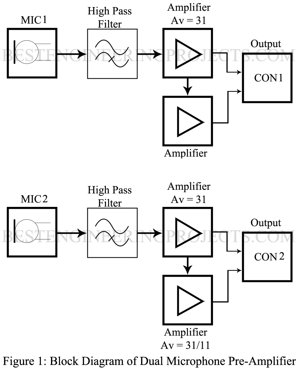
Block Diagram of Dual Microphone Preamplifier Circuit
Block Diagram is shown in figure 1. The output of the microphone is first filtered using a high pass filter and further amplified using a non-inverter amplifier. Two amplifiers are used for a single microphone as shown in the block diagram. The output of the first amplifier is set to gain (AV) 31, where the second amplifier has two gains i.e. 31 and 11. The output of these amplifiers is connected to a connector. The circuit for the second microphone is identical as shown in the block diagram.
Circuit Description and Working of the Dual Microphone Preamplifier circuit
The circuit diagram of the dual microphone amplifier is built around a low-power quad op-amp MP604. Op-Amp MP604 contains four individual op-amp. Two op-amps are used to amplify the output of MIC1 whereas the other two op-amps are used to amplify the output of MIC2. These op-amps are configured in non-inverting mode.
The output of the microphone is passed through a high pass filter designed using a capacitor and resistor. This filter acts as a DC filter i.e. it filters out all the DC signals. This filtered signal is given to non-inverting input for amplification.
Non-Inverting Amplifier Circuit and Its Gain Calculation
The circuit of the non-inverting amplifier is shown in figure 2. As it contains two resistors named input resistor and feedback resistor. The value of these resistors is set as per the requirement of gain. Let’s calculate the value of the resistor for gains 31 and 11.
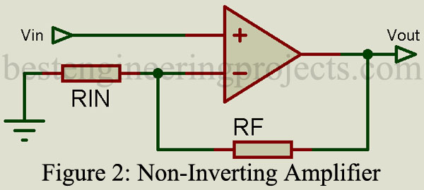
The calculation for gain 31
Gain of non-inverting amplifier (AV) = 
Let Rin = 1k, and AV = 31
Putting these value in above equation


Calculation for gain 11
Let Rin = 1k, and AV = 11
Putting these value in above equation


Complete Circuit Diagram
The complete circuit diagram of the circuit Dual microphone amplifier is shown in figure 3. As you can see there are two identical circuits each for an individual microphone. MIC1, amplifier U1:A and U1:B, Transistor T1 complete the pre-amplifier section for the first microphone whereas MIC2, amplifier U1:C, and U1:D, Transistor T2 complete the pre-amplifier section for the second microphone. So, here only one circuit is described because the other circuit is just a replica.
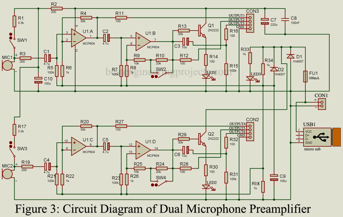
The output of amplifier U1:A is given to non-inverting input (pin 5) of U1:B through a capacitor. Amplifier U1:B provides an output at gain 31 and gain 11. If switch SW2 is closed gain of U1:B will be 11 and if switch SW2 is open gain will be 31. There are two types of output obtained from pin 7 (Output of U1:B) i.e. output with DC component and Output without DC Component.
Output1 and Output2 contain DC components of the value of Vcc/2 whereas output 3 does not contain DC components. Similarly, Output 4 and 5 of MIC2 contains DC components of value Vcc/2 and output 6 does not contain DC components. All output is protected by a series resistor of 100-Ohm.
Output U1:B is also connected to the base of the transistor T1 which further drives LED LED1. This LED (LED1) indicates the level of the output signal from microphone MIC1. Similarly, LED2 indicates the level of the output signal from microphone MIC2.
Switch SW1 and SW3 are given here to select the power source for the microphone. If the microphone needs an external power supply then only these switches (SW1 and SW3) will be closed otherwise these switches kept open.
Power Supply: You can power this circuit either by USB or by DC power supply ranging from 2.7V to 5.5V (CON3). The power supply is indicated by LED3. Diode D1 protects the circuit from reverse polarity whereas the fuse protects it from short circuits. For biasing of op-amp Vcc/2 power supply is required. This can be obtained using resistors R34 and R18, capacitor C9, and diode D2.
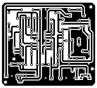
Figure 4: Solder Side PCB of Dual Microphone Preamplifier
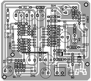
Figure 5: Component Side of Dual Microphone preamplifier
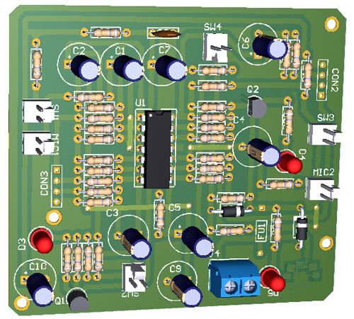
Figure 6: Component Side View of PCB
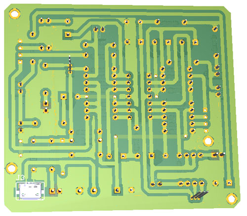
Figure 7: Solder Side View of PCB
PCB Diagram: PCB is designed using Altium Design Suite, Solder side PCB and Component Side PCB is shown in Figures 4 and 5 where the 3D view of PCB is shown in Figures 6 and 7. Micro USB used here is of SMD type and must be connected to solder side as shown in figure 7. Download the actual solder side and component side PCB from the link given below.
Components List of Dual Microphone Preamplifier Circuit
| Resistor (all ¼-watt, ± 5% Carbon) |
| R1, R17 = 3.3KΩ
R2, R3, R19 = 200Ω R4, R13, R20, R29 = 30KΩ R5, R7, R15, R21, R23, R31 = 100KΩ R6, R8, R18, R22, R26, R33, R34 = 1KΩ R9, R25 = 10KΩ R10, R24 = 20KΩ R11, R12, R14, R16, R27, R28, R30, R32 = 100Ω |
| Capacitor |
| C1, C2, C4, C5 = 4.7µF/16V (Electrolytic Capacitor)
C3, C6 = 10µF/16V (Electrolytic Capacitor) C7 = 220µF/16V (Electrolytic Capacitor) C8 = 100nF (Ceramic Disc) C9, C10 = 100µF/16V (Electrolytic Capacitor) |
| Semiconductor |
| U1 (A, B, C, D) = MCP604 (Quad Low Power Op-Amp)
Q1, Q2 = 2N2222 (General Purpose Low Power Transistor) D1, D2 = 1N4007 (General Purpose Switching Diode) LED1, LED2, LED3 = Any color 5mm LED |
| Miscellaneous |
| MIC1, MIC2 = Electret Microphone
FU1 = 100mA Fuse SW1, SW2, SW3, SW4 = ON/OFF Switch USB1 = Micro USB CON1 = 2-pin terminal connector CON2, CON3 = 4-pin connector |
Please give some CCTV camera ckt.