Lithium Iron Phosphate LiFePO4 or Li-Fe battery is the latest generation of Li-ion battery and is popular among electronics hobbyists because of its features like high discharge current rate, safety and it is the least toxic of all battery types. Also, these batteries are safer because of the chemistry involved to make them. It contains a very stable composition of phosphate as a result longer life span of the battery can be achieved. However, the latest generation Li batteries are non-inflammable and are capable of bearing extreme conditions. In this article, we are going to discuss a DIY LiFePO4 battery charger circuit i.e. one can make this simple charger circuit with easily available electronics components.
There are various rather types of battery charger circuits available in Best Engineering Projects, some are listed below:
Circuit Description of LiFePO4 Battery Charger Circuit
The LiFePO4 battery charger circuit (Figure 1) is designed around an Op-amp LM358, a PNP transistor S8550, a diode (1N4007), and a few other passive components like resistor, capacitor, etc.
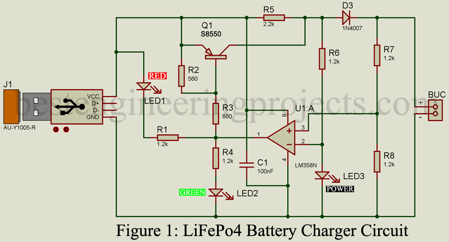
Op-Amp LM358 is used here because it is known for having large dc voltage gain, large out and ut voltage logic swing (VLS), and has a wide range of power supplies for both single and dual power supplies. Op-amp is used herein comparator mode, it compares the voltage output from a battery with supply voltage. PNP Transistor T1 acts as a switch that only turns ON when the voltage of the battery to be charged is lower than the predefined voltage. The switching action of the transistor T1 is controlled by Op-Amp. The output voltage from the transistor is passed through diode D1. There are two roles of diode D1, one to stop the flow of current from the battery to the circuit and another to drop the voltage to a specific level.
This circuit consists of three LEDs, two RED Colors, and a Colors color LED. Glowing LED1 (Red Color) indicates the battery is charging whereas glowwhereasED2 (Green Color) indicates the battery is fully charged. Glowing LED3 (Red Color) indicated power is available to the circuit.
Resistors R7 combined with resistor R8 to provide reference voltage from battery to non-inverting input (pin 3) of comparator circuit built using Op-Amp LM358. Where resistor R6 combines with LED3 (Power LED) provides a fixed reference voltage to inverting input (Pin 2) of Op-Amp LM358.
This circuit is designed as a single-cell LiFePO4 (3.2V) charger, which gives an expected output of 3.6 V.
Working of the Circuit
When the battery to be charged is connected to BUC, Op-Amp gets voltage from the battery to its non-inverting terminal. A fixed reference voltage is available at inverting input (Pin 2) and signal voltage from the battery is available at the non-inverting input (Pin 3). The voltage at the non-inverting terminal is variable and depends upon battery voltage
Case 1: When the battery is not fully charged:
When the voltage at the non-inverting input is less than the reference voltage, the output of Op-Amp becomes low, which further drives transistor T1 in ON State. As a result, the battery starts to charge and LED1 becomes ON.
Case 2: When the battery is fully charged:
When the voltage at the non-inverting terminal is more than the reference voltage, the output of the Op-amp becomes high, which further drives transistor T1 in the OFF state, As a result, the full charge indicator LED (LED2) starts to glow. No voltage will follow the battery because the voltage at the anode is lower than the voltage at the cathode of the diode.
While designing this circuit we must assure that the component values must be equal to the component list. To output, the values of resistors(R2, R7, and R8) can be changed.
Thus, this circuit provides an output of 3.6 V @ 250 mA which is appropriate for a battery up to 3.2 V @ 2500 mAH.
We can note this, LED1, a LED indicating charging may flicker which may be due to the comparator and it is so. So, for troubleshooting such problems a comparator IC with hysteresis can be used.
PCB Diagram
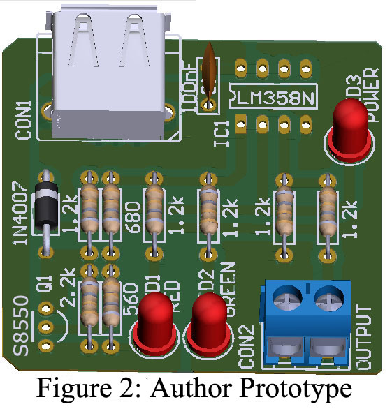
PCB Diagram of LiFePO4 Battery Charger circuit is designed using Altium Designer. Figure 3 shows the solder side whereas figure 4 shows the component side of the PCB diagram. The actual size of the Solder side and component side PCB can be downloaded from the link given below.

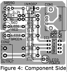
Click Here to Download Solder Side and Component Side PCB.
To battery safely, a holder of nice quality is recommended and for long-term use, a satisfying enclosure for a LiFeO4 battery charger is also recommended.
After finishing the complete construction, we provide a power supply of stable DC 5 V supplied by a USB port, or, a regulated power supply, or, a USB power adaptor. If our circuit is fabricated correctly, then LED2 and LED3 light up. Now, when a voltmeter is connected across the battery holder CON2, a DC voltage value near 3.6 V is seen. Then, after we place the discharged LiFeO4 battery in its holder, we see that LED1 will glow, indicating the battery started to charge.
A Very nice circuit I have tried a charger board from China as it was the only one I could find at the time but now I have found yours I think I will make one as the Chinese one failed after 3 months of use so thank you for your project and sharing your work it is much appreciated
Thanks, Bob
One disadvantage of this schematic is that there is always a discharging of the battery via R7/R8, so the charger cannot remain connected after charging is complete, because it consumes power from the battery.