There are lots of 12V Lead Acid Battery Charger Circuit available over the internet but does not include a battery status indicator. If you wish to know the status of the battery like dead, charged, or charging you need an extra circuit. In order to solve these problems, we combined three different circuits and hence do three different dedicated jobs like charging the battery, indicating the status of the battery, and also have a dedicated port for variable power supply connector of bench power supply in case you need. This circuit can charge the battery from 50 Ah to 100 Ah with proper visual and audio indication.
Specifications and Advantages of 12V Lead Acid Battery Charger Circuit
- Can charge the 12V Lead-Acid battery from 50Ah to 100Ah.
- Dedicated variable power supply port up to 18V DC at maximum 5A.
- Automatic detects the battery and charges it with the appropriate voltage.
- No output is available at the variable power supply connector when the battery is connected.
- Dedicated LED and alarm for reverse polarity connection of the battery.
- Dedicated LED for indication of different status of the battery. (dead battery, healthy battery, charging, full charge).
- Charge the battery at 14.2V and maintain 13.4V when it is fully charged.
Circuit Description of 12V Lead Acid Battery Charger Circuit
The circuit diagram of the 12V lead-acid battery charger is shown in figure 1. This circuit is built around a fixed voltage regulator, variable voltage regulator, dual operational amplifier IC, Transistor, Relay, Transformer, and a few other electronic components.
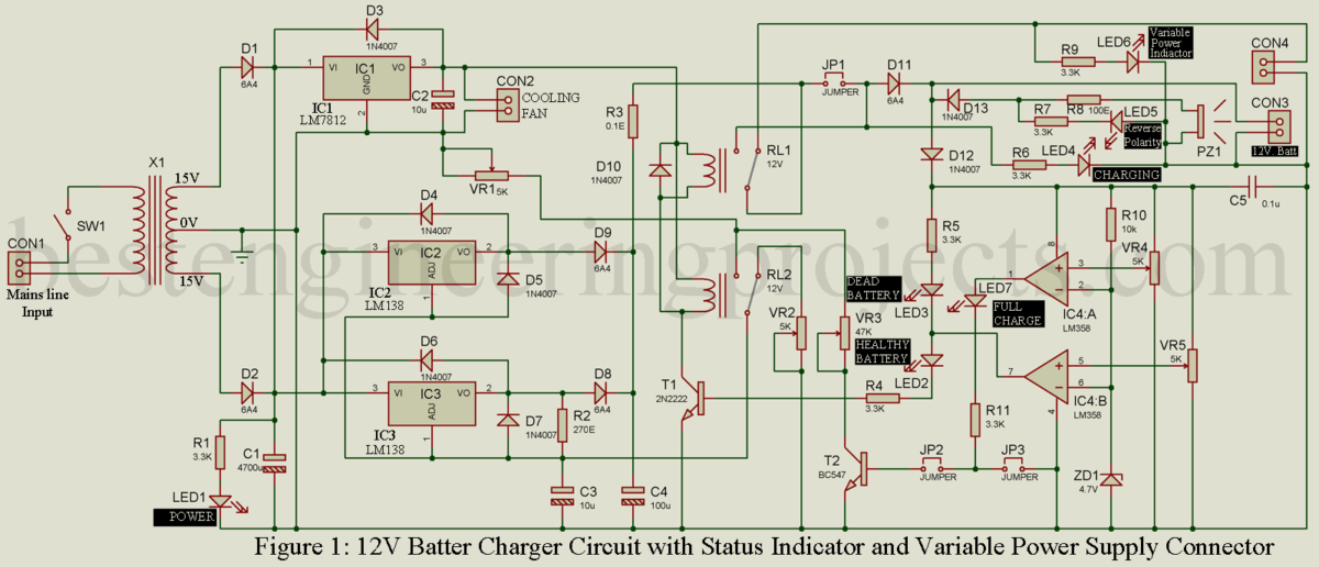
Rectifier Section:
220V AC mains supply is given to primary winding of stepdown center-tap transformer X1 which lowers the voltage to 15V-0-15V AC. This 15V-0-15V AC is rectified by a full-wave rectifier designed using two diodes (D1 and D2) and filtered using one 4700uF electrolytic capacitor (C1). LED1 indicates the presence of mains supply where resistor R1 limits the current and dropout the extra voltage.
Fixed Voltage regulator Section:
The fixed voltage regulator is designed around 12V fixed voltage regulator LM7812. Unregulated DC volt is given to voltage input pin (pin 1) of IC1 and a 12V regulated power supply is available at pin voltage output pin (pin 3). Capacitor C2 connected at output filters the unregulated part if available. This 12V fixed DC voltage is used to operate the cooling fan and both relay (RL1 and RL2). Diode D3 protects the voltage regulator from reverse voltage.
Variable voltage regulator Section
Variable voltage regulator is designed using two LM138 IC connected in parallel in order to handle high current. Unregulated DC volts are given to the voltage input pin (Pin 3) of IC2 and IC3. The output voltage is adjusted by two different variable resistors VR1 and VR2. Output voltage at variable power supply is controlled by variable resistor VR2 whereas the voltage at battery charger port is adjusted by variable resistor VR1. Diode D5 to D7 are used here for protecting the variable voltage regulator IC (IC2 and IC2) where diodes D8 and D9 block the flow of voltage from the battery back to the voltage regulator. The selection of variable resistors is done by relay RL2.
Other battery charger circuits available on bestengineeringprojects.com are:
1. Arduino Controlled 12V battery charger circuit
2. 12 V Battery Charger with overcharge and deep-discharge protecting
3. Microcontroller Based Solar Charger
4. 12v, 7Ah Smart Battery Charger with PCB Diagram
5. Automatic battery float charger circuit
Case 1: Battery Charging Section
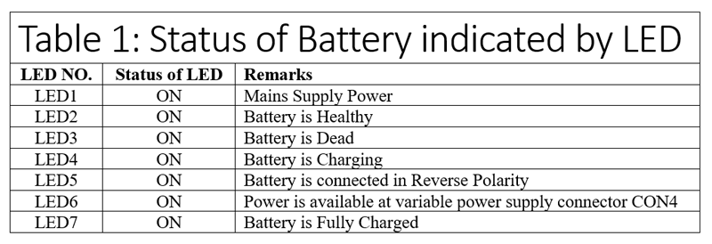
When the battery is connected to the connector CON3 operational amplifier IC4 gets a power supply. Op-amp LM358 is a dual op-amp (IC4:A and IC4:B) and is configured in voltage comparator mode. A fixed voltage is given to inverting pin of both the amplifier (pin 2 and pin 6) where the non-inverting pin gets variable voltage according to battery voltage. OP-AMP2 (IC4:B) is set in order to determine whether the battery is dead or healthy. If the battery is dead i.e. output voltage is less than 9V. When the battery voltage is less than 9V output of the comparator (IC4:B) at pin 7 becomes low as a result LED3 starts to glow. Glowing LED3 indicates the battery is dead. When the battery voltage is greater than 9V then the output of the comparator (IC4:B) is high as result LED4 starts to glow. Glowing LED4 indicates the battery is healthy. When the output of IC4:B is high, transistor T1 (2N2222) gets operating voltage at its base and thus starts to conduct as a result both the relay (RL1 and RL2) is energized. When the relay gets energized its common pin start to connect with the N/O pin as a result output is available at the battery charger connector (CON4) and the battery starts to charge.
When the battery is fully charged voltage available at the non-inverting pin (pin 3) becomes higher than the voltage at inverting pin (pin 2) as a result output at pin 1 becomes high and LED7 start to glow indicating the battery is fully charged. This high output at pin 1 activates transistor T2 (BC547) and some voltage flow to the ground which lower some voltage (approx 0.8) at the output pin of the variable voltage regulator (IC2 and IC3). Thus, it maintains 13.4V at CON3 when the battery is fully charged.
Case 2: Variable Power Supply Section
When the battery is not connected for charging operational amplifier IC does not get a power supply as a result transistor T1 does not conduct and both the relay (RL1 and RL2) are in a de-energized state. At this time voltage is available at the variable power supply connector (CON4). Variable resistor VR2 is used to adjust output voltage at this connector.
When the battery is connected in reverse polarity diode D13 starts to connect as result LED5 start to conduct with sound. Thus, glowing LED5 with alarm indicates the battery is connected in opposite polarity.
LED6 is used to indicate the power supply available at variable power supply connector CON4. The brightness of LED6 varies according to the output voltage at CON4.
Configuration of 12V Lead Acid Battery Charger Circuit
- Connect all the components as shown in the circuit diagram.
- Remove the jumper JP2 and JP3 while connecting jumper JP1 and switch SW1 ON.
- Adjust variable resistor VR5 such a way LED2 and LED3 are ON and OFF alternately while changing the state of both the relay (energized and de-energized).
- Adjust variable resistor VR1 in such a way that voltage available at VCC pin of IC4 (pin 8) with respect to the ground must be battery full charged voltage (13.4V DC).
- Connect Jumper JP3 and adjust VR4 in such a way that LED7 start to glow.
- Again, adjust VR1 in such a way that the voltage available at the VCC pin of IC4 (pin 8) with respect to the ground must be 14.2V.
- Now Connect jumper JP2 and adjust variable resistor VR3 till voltage at VCC pin of IC4 (pin 8) with respect to ground is 13.4V DC.
- Now, remove the jumper JP1 and your charger circuit is ready to use.
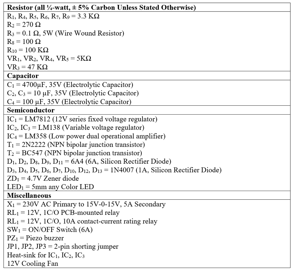
Component Required for 12V Lead Acid Battery Charger Circuit
PCB Design: The PCB diagram for 12V Lead Acid Battery Charger Circuit is designed using Proteus 8.1. The actual size solder side and component side PCB designs are shown below. As this PCB is a single layer, thus we require a jumper on the component side as shown in the PCB diagram below. You can download the PCB diagram in PDF format from the link below.

Figure 2: Actual size solder side PCB diagram of 12V lead acid battery charger circuit

Figure 3: Actual size component side PCB diagram of 12V lead acid battery charger circuit
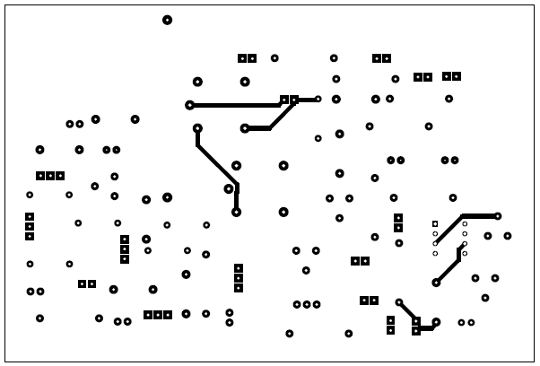
Figure 4: Jumper placement in PCB diagram
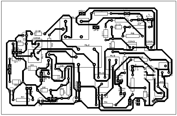
Figure 5: Tracing Path for PCB
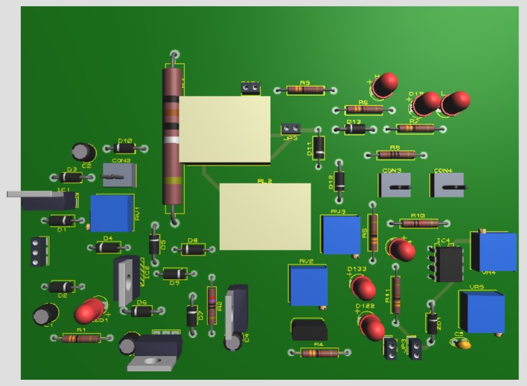
Figure 6: PCB Prototype for 12V Lead-acid battery charger circuit
Click Here to Download the PCB diagram in PDF Format
Please share a Proteus File of Circuit
Hello can one use these circuit designs for a project working on
Yes, you can use it.
The circuit is 100% tested.
replacement for lm138? thanks
Can You share a proteus file please?