DIY Arduino Controlled Guitar Pedal: Here in this article, you will learn how to design a programmable pedal for guitar using an Arduino UNO board. For understanding this project, you do not need deep knowledge of programming, digital signal processing, and electronic hardware. All you need is a little familiar with soldering and C programming. We have described the project in a very detailed and simple manner. This DIY Arduino Controller Guitar pedal is designed for hobbyists and those who took interest in music and guitar.
Features of DIY Arduino Controlled Guitar Pedal
- Dedicated footswitch and other switches for volume control for easy to use.
- No dedicated external power supply need i.e. it took the required power (voltage and current) from the Arduino board.
- For better visual indication and visual effect dedicated LED is connected in a programable manner.
- Dedicated input and output filter for filtering distortion and noise.
- Single Rail-to-Rail amplifier is used for input and output for given better amplification.
- 10-bit ADC of Arduino board is used for changing analog signal from guitar to digital signal used in DSP.
- 16-bit output stage for better bit resolutions.
Components Parts of DIY Arduino Controlled Guitar Pedal
| Resistor (all ¼-watt, ± 1% Carbon Unless Stated Otherwise) |
| R1, R2 = 1 MΩ
R3, R4, R6, R7, R8, R10, R11 = 4.7 KΩ R5, R12, R13 = 100 KΩ R9 = 1.2 MΩ VR1 = 500 KΩ |
| Capacitors |
| C1, C10 = 0.1 µF (Ceramic Disc)
C2, C5, C6, C7, C8 = 6.8 nF (Ceramic Disc) C3, C9, C11 = 4.7 µF, 16V (Electrolytic Capacitor) C4 = 270 pF (Ceramic Disc) |
| Semiconductors |
| Arduino UNO Board
IC1 = TL972 (Rail-to-Rail Operational Amplifier) LED1 = 3mm any color LED |
| Miscellaneous |
| SW1 (A, B) = 3DPT Foot Switch
SW2, SW3 = Push Button Switch SW4 = Toggle Switch CON1, CON2 = ¼ Jack Audio |
Circuit Description of DIY Arduino Controlled Guitar Pedal
The circuit diagram of DIY Arduino Controlled Guitar Pedal is shown in figure 1, build around Arduino UNO board, dual operational amplifier IC TL972 and a few other active and passive electronic components.

Guitar Input Amplifier Section:
The signal from the guitar is given through the audio jack (CON1) to the circuit through a 3DPT foot switch as shown in the circuit diagram. The signal from the guitar is given to the non-inverting input of operational amplifier IC (pin 3) through various filter networks. Capacitor C1 is decoupled capacitor and filter out the DC component available in the guitar signal. The reference voltage of 2.5V is given through resistor R2 for virtual ground. These signals are filtered by a low pass filter network built using resistor R3 and capacitor C2. Inverting pin is grounded through RC series network.
The gain of the input audio amplifier is adjustable. Variable resistor VR1 does the job of adjusting gain from 1 to 21. As you can see two other low pass filter networks are connected in the feedback path and output. The basic job of these three low pass filter circuits is to filter out harmonics present in the signal. If these harmonic signals are not removed then it may create aliasing at the time of conversion to a digital signal. The cutoff frequency is about 5KHz.
Arduino UNO takes the input through analog pin A0, processes it, and produces PWM output. Two push-button switches are used here to control the volume. You can decrease the volume by pressing switch SW2 and increase it by pressing switch SW3.
LED is used here to show the effect where resistor R7 is a current limiting resistor. This resistor controls the voltage and current supplied to the LED.
Output Amplifier Section:
ATmega328 microcontroller is used on Arduino UNO board which is an 8-bit microcontroller but here we are using 16-bit output. For 16-bit output, we are combining two PWM outputs in parallel as shown in the circuit diagram. This output is filtered using a 3rd order sallen key low pass filter. This filter is designed to filter out the harmonic signal above the cutoff frequency (FC = 5KHz).
The output of this filter is connected to the footswitch through the electrolytic capacitor. Output audio jack is connected at one pole of footswitch as shown in the figure.
On Bypass, a path is created here which directly passes the guitar output to the speaker without modifying/amplifying it. When foot switch SW1 is pressed the guitar output is directly given to the speaker which is indicated by glowing LED1.
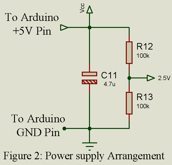
Power Supply arrangement
No external power supply circuit is required. 5V power is obtained from the 5V pin of the Arduino UNO board. Capacitor C11 filter the ripple available in the power supply line. For the virtual ground of operational amplifier IC1 2.5V power supply is designed using a voltage divider network. Two resistors R12 and R13 work as voltage dividers and produce 2.5V DC output and are given to the resistor R2 as shown in the circuit diagram.
Software for DIY Arduino Controlled Guitar Pedal
The software code is written in Arduino programming language and is compiled using Arduino IDE. You can directly download the complete code used in the guitar pedal.
Click Here to Download the Software Code
Good day
Thanks for sharing this project and just for curiosity and before I start to dive into this project, does it work also on Arduino Nano ?
Thanks
Armando
Hi. You can use Arduino UNO as well as Arduino nano, without modifying code and/or circuit because both of these boards use similar microcontrollers i.e. AtMega328.
Hello, thank you very much for sharing such a valuable project. Tell me, does this device have the ability to switch between effects or can you select only one programmed