The project ‘Microcontroller Based Solar Charger’ has been so popular, that everyone knows about it. Here we will discuss the construction details and areas where this project is applicable.
With excessive non-renewable energy consumption, we humans are facing plentiful difficulties. Renewable sources of energy are considered our only hope to rise from this situation. Solar energy is one of them which have spread all over for its easy availability, effective cost, and reliability. The project, ‘Microcontroller Based Solar Charger’ is the finest example to demonstrate the easy utilization of resources found around us and extract as much as benefits possible from it.
Recent lighting systems which include solar lanterns, home lighting systems, streetlights, garden lights, water heaters, and solar power packs, drive power from solar energy. If you are thinking about how that natural form of energy is transformed to power these devices, then let me tell you. This transforming system comprises just four chief components: solar photovoltaic (PV) module, rechargeable battery, solar charge controller, and load.
Here, the PV module traps the rays, the rechargeable battery acts as a storehouse of energy and the load comprises a device to be powered. The solar charge controller takes into account the fact that enough charge is stored in the battery as per the capacity of the rechargeable battery. Hence, it plays a vital role in the overall system being established as a crucial link between the solar panel, battery, and load.
The common component LCD depicts the current status of the system.
Circuit and Working of Microcontroller Based Solar Charger
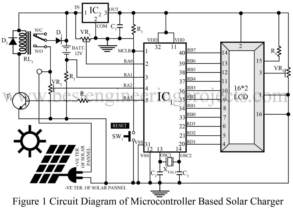
The project ‘Microcontroller Based Solar Charger’ is fabricated around PIC16F877A (IC1) microcontroller as the chief component. Besides that, regulator 7805 (IC2) and a few discrete components are also employed in the project. The entire layout of the circuit of the Microcontroller Based Solar Charger is illustrated in figure 1.
Talking about the central component; PIC16F877A, it provides an ideal solution for hobby and industrial development, proving itself worthy of popularity and power at the same time. This IC employs Harvard architecture. The charge control operation is carried out by this component through the solar panel.
The fascinating fact about the core component; the 8-bit microcontroller is that it consumes low power and yet offers the best performance. Multiple features like 8kB flash, 256 bytes of EEPROM, 368 bytes of RAM, 33 input/output (I/O) pins, 10-bit 8-channel analog-to-digital converter (ADC), and three timers make this device more appealing. To ensure reliability, it also constitutes a watchdog timer with its on-chip R-C oscillator which is essential in a synchronous I2C interface. The number of simple instructions, this device can handle is 35. The majority of these instructions are single-cycle, and branches have two-cycle instructions.
For LCD interface with a microcontroller, data pins D0-D7 of the LCD module are connected with port pins RB0-RB7 of the microcontroller. Similarly, RS (register-select), R/W (read/write), and E (enable) of the LCD are connected to port pins RD1, RD2, and RD3. For contrast control, preset VR3 is used. To perform a manual reset operation, switch SW1 is included in the circuit. The basic clock frequency required for the microcontroller is provided by a combination of a 4MHz crystal along with two 33pF capacitors.
Three particular pins of the microcontroller monitor the parameter status. These port pins RA0, RA1, and RA2 collect required input to continuously check on battery voltage, charge current, and solar panel voltage, respectively. And, thus on basis of the information collected, the overall process is controlled and meaningful information is displayed on the LCD module. The connection between solar panel and battery is established as soon as the port pin RA3 goes high, then transistor T1 becomes saturated and relay RL1 energizes.
The +5 volt regulated supply for the microcontroller and LCD module is provided by the Regulator 7805. Based on the voltage, the charging process can be carried out in two distinct ways- boost and trickle. 12V is the defining parameter that determines if the battery is charged in boost mode or trickle mode. For less than 12V, charging is done in boost mode and for higher, trickle mode is activated. In trickle mode, the battery is charged at a discharge rate.
The project ‘Microcontroller Based Solar Charger’ also provides required information about the limit of energy collected by the solar panel. This information is utilized to approximate the exact amount of power that can be extracted from the sun itself.
Construction and testing of Microcontroller Based Solar Charger
Fig. 2 and Fig.3 provide the precise single-side PCB layout for the PIC16F877A microcontroller-based solar charger and its complete component layout respectively. It is strongly recommended to perform the assembling process on a PCB to avoid time and assembly errors to some extent. However, one must be extra careful during assembling the components, and overlooked errors must be double-checked. To eradicate possible damage to the IC during assembling, an IC base is used. To ensure safety before placing the IC, the supply voltage (5V) is checked at test point TP1 as shown in fig.
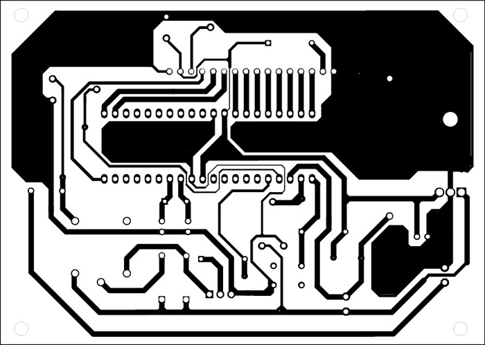
Figure 2: Solder Side PCB of Microcontroller Based Solar Charger
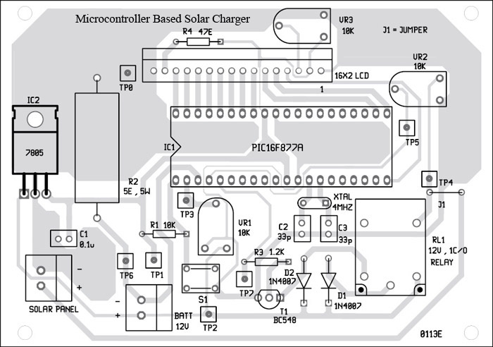
Figure 3: Component Side PCB of Microcontroller Based Solar Charger
To evade further complications, before implementing the circuit, the system is calibrated for battery and solar voltages. And, this is done in the following ways:-
Battery voltage | Microcontroller Based Solar Charger
Disconnect the battery used in the project. Then apply 20V at the input point of IC2 (7805) concerning the ground. At pin 2 of IC1 (PIC16F877), check on the voltage value using a multimeter. After that necessary adjustment to the circuit is done by varying the preset VR1 to get 5V. Again, a voltage test at pin 4 of IC1 (PIC16F877) is done to ensure that the voltage at that point is 5V. When the batteries are connected back to the system, the voltage value at pin 2 of IC1 (PIC16F877) must be approximately 3V.
Solar voltage | Microcontroller Based Solar Charger
Confiscate the solar panel from the circuit. A 12V battery is connected at a positive terminal of solar concerning the ground and then the voltage level at pin 4 of IC1 (PIC16F877) is monitored. Now, the preset VR2 is adjusted to get 3V. At pin 7 of IC1 (PIC16F877), we can check if the relay RL1 is enabled or not.
After all these calibration steps, the ‘Microcontroller Based Solar Charger’ circuit is ready to be implanted. The circuit generates solar power and that value is calculated and displayed on LCD in watts per second. To get the energy in terms of watts-second, the power is integrated.
LCDs list of information as per the sequence given below:
- Battery voltage (millivolts)
2. Battery current (milliamperes)
3. Energy (watt-seconds)
4. Power (watts)
5. Solar-panel voltage (millivolts)
6. Charger mode: boost or trickle
Software code of Microcontroller Based Solar Charger
The program code is written in simple; Basic language and thus is easy to understand. PIC Simulator IDE from Oshonsoft is used to compile the project code. The IDE is a simple software that provides an easy way to program the system using Basic commands and then generate the corresponding hex code once it is compiled. Another device called program burner or programmer is employed to burn/load thus generated hex code is into the microcontroller.
The circuit ‘Microcontroller Based Solar Charger’ firstly detects the voltage on the solar panel, if the voltage exceeds 12.6 volts, then the next instruction on the flowchart is followed. And, if the voltage readings fall below 12.6 volts, a piece of information; “Low Solar Volts” is displayed on the LCD module and it repeats itself unless the voltage becomes greater than the defined voltage i.e. 12.6V.
In the second stage, the battery voltage is monitored, and depending on the results, the charging mode; boost or trickle mode is decided. As, stated earlier, for battery voltage exceeding 12V, trickle mode is activated and for below 12V, boost mode is triggered. In the early hours, the watt-hour reading from EEPROM is also read, which provides an approximation of the power acquired from the sun.
CLICK HERE TO DOWNLOAD THE SOFTWARE CODE
The project ‘Microcontroller Based Solar Charger’ includes a timer that generates an interrupt every 65.56 ms. In ISR (Interrupt Service Routine), the 15th count refers that the power and energy of the system are calculated every 65.56×15 =983.4 ms i.e. approximately 1 second. The power absorbed is integrated every second to obtain the energy in terms of watt-seconds. These watt-hour readings are stored directly in the EEPROM of the microcontroller to avoid data loss during power failure. Again, this can lead to over-write in EEPROM. To solve this problem, writing to EEPROM is done as programmed every 30 minutes.
Check out more other battery charger circuits posted on bestengineeringprojects.com
- 12v, 7Ah Smart Battery Charger with PCB Diagram
- 12 V Battery Charger with overcharge and deep-discharge protecting
- Automatic battery float charger circuit
PAETS LIST OF MICROCONTROLLER BASED SOLAR CHARGER
| Resistor (all ¼-watt, ± 5% Carbon) |
| R1 = 10 KΩ
R2 = 5 Ω, 5W R3 = 1.2 KΩ R4 = 47 Ω VR1 – VR3 = 10 KΩ Preset |
| Capacitor |
| C1 = 0.1 µF (Ceramic Disc)
C2, C3 = 33 pF (Ceramic Disc) |
| Semiconductors |
| IC1 = PIC16F877A (Microcontroller)
IC2 = 7805 (5V Series linear voltage regulator) T1 = BC548 (general-purpose NPN bipolar junction transistor) D1, D2 = 1N4007 (Rectifier Diode) |
| Miscellaneous |
| SW1 = Push-to-on Tactile Switch
RL1 = 12V, Single-changeover Relay XTAL1 = 4 MHz Crystal LCD1 = 16-character*2-line LCD module BATT1 = 12V Lead-acid Battery Solar Panel |
where can i get 16 pin lcd display from proteus? somebody help me.
You don’t need 16 pin LCD because pin no 15 and 16 is for back light, and in simulation you don’t need back light.
https://uploads.disquscdn.com/images/48d155806ea49a6a7f1b4b6629aa634cbd46cc3624ef13745fb0013de029cc6b.png
but there is something attached to no.15 pin just like in the picture. then how to solve it? help me!
That’s the current limiting resistor as we used in led in order to protect LED. It’s nothing other then a current limiter resistor for back light.
so, i can use the 14 pin lcd for the circuit? for example the LM016L lcd display.
Yes, but match the pin like digital pin D0, D1, D3 etc.
if you dont mind, can i have your email to personally contact you for further information about this project?
i already build the circuit just like in the picture include the hex file in microprocessor, but why did the lcd only on without any text in the lcd?
Firdaus Mangsor, Please read the complete article, your all queries will me solved.
https://uploads.disquscdn.com/images/537be458c9b2839cb2789163d94086dacee6c48ebaa82d9967d9aa1a629f74f2.png
What PIC pin should be connect with LCD pin 4,5 and 6? Help me!
sir, can i have the c source code file for this project. when i put the hex file you give in this post, it did not working properly. help me sir!
Is there any C code for this project?
Please which PCB software did you use in designing this board?. . Thanks