Sound Operated Intruder Alarm with extra features like a flashlight, circuit diagram, description with working principle, and parts list.
Introduction to Sound Operated Intruder Alarm with Flash
If you have already gone through the previous project Op-amp 741 Based Sound operated Light on our website, then for you this project is a transformation of that generalized project into a specialized intruder’s alarm project. Why should one invest much effort, time, and money to recreate a new circuit when a slight modification to the existing project works fine? This is the core principle in electronics which is followed everywhere. And, we followed the same pattern. The sound of the opening of the door, the clicking sound of a key in the lock, etc are the triggering factors of this circuit. In addition to features provided by the Op-am 741 Based Sound Operated Light project, this one offers extra properties of light flashing and alternating audio tone indications which help in preventing robbery.
Circuit Description of Sound Operated Intruder Alarm with Flash
As stated in the early project Op-amp 741 Based Sound operated Light, this article also includes J-K flip-flop IC as a core component. This circuit is identical to the previous circuit up to the flip-flop output. Therefore, the output of op-amp and the output of flip-flop (Q), are maintained at a low state in the initial condition. Now, here comes the part that makes this project a little different from the previous one. It encompasses an extra IC-IC3 which is a widely used timer IC 555. It is wired as an astable multivibrator. This IC gets reset as the reset terminal (Pin-4) is made low.
(At pin 3 of IC2 a DPDT relay can be used and the description is given here) Due to this, the transistor (Q1) reaches cut-off mode and hence relay is de-energized. And, so the normally open contacts of relay remain in the same state. Out of the two relay contacts, contact-1 keeps the lamp off, and the other one; contact-2 is connected along the pathway in between the output pin of another astable multivibrator (IC4) and the speaker prevents the output signal of IC4 from reaching the speaker. This situation reflects there are no intruders in the surrounding.
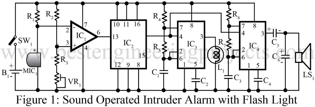
Secondly, when the circuit detects any sound pulse around the vicinity, it generates a positive pulse at the output terminal of the op-amp and provides a clock to the flip-flop. Then, the toggle flip-flop’s output is altered i.e. if low initially then high, and vice-versa. In correspondence to this, the flip-flop output becomes high for certain intervals until the next sound pulse is detected. An astable multivibrator built around IC3 gets activated with high output from the flip-flop. Finally, the relay coil is driven on/off by the output obtained from the astable multivibrator. Mathematically, the on and off periods of the relay are given by the following expressions:
On-time= 0.69 (R4+R5)C2
Off-time= 0.69 R5 C2
For a given value of resistor and capacitor in the table, the on and off- times for the relay are calculated to be 1.4 and 0.7 seconds respectively. During the energized condition of the relay, contact-1 causes the bulb to glow as it supplies the required AC power to the bulb. And, the other contact-2 connects the astable output to the speaker, and the audio tone is heard. The frequency of this tone can be adjusted by the formula:
f=1/(0.69(R6+R7 C4)+R7C4)
Following the table, this value is found to be 500 HZ.
The working phenomenon of the project Sound Operated Intruder Alarm with Flash can be described in a few words. As long as the toggle flip-flop output is high, the light flashes and the audio tone is heard. Again, when the next pulse is found by the gadget, the flip-flop output is toggled and falls low, then the light turns off and the tone cannot be heard anymore.
Check out other interesting sound generator circuits using timer IC 555 using bestengineeringprojects.com
- Simple Drummer Project Using Timer 555
- Fire Alarm Using Thermistor and NE555
- Machine Sound Generator Using 555 Timer IC
- Beeper for Automobile Flasher Using 555
- Grasshopper Sound Generator Circuit using 555 Timer IC
PARTS LIST OF SOUND OPERATED INTRUDER ALARM WITH FLASH |
| Resistors |
| R1, R6, R7 = 10KΩ, 1/4W
R2 = 1KΩ, 1/4W R3 = 470Ω, 1/4W R4, R5 = 470KΩ, 1/4W VR1 = 1KΩ Preset |
| Capacitor |
| C1: 2.2 µF, 25V (Electrolytic Capacitor)
C2, C4 = 0.01 µF (Ceramic Disc) C3 = 0.1 µF (Ceramic Disc) C5 = 100 µF, 16V (Electrolytic Capacitor) C6 = 10 µF, 16V (Electrolytic Capacitor) |
| Semiconductors |
| IC1 = LM741 (Operational Amplifier)
IC2 = CD4027B (Dual J-K Flip-Flop IC) IC3, IC4 = NE555 (Timer IC) |
| Miscellaneous |
| MIC1 = Condenser Microphone
B1 = 12V Battery LS1 = 4Ω Speaker L1 = 12V Lamp (bulb) SW1 = On/Off Switch |
sir, can i have the PCB layout of this circuit (Sound Operated Intruder Alarm with Flash Light)
https://uploads.disquscdn.com/images/9fd90a1c9077684c5660be19439d668c379baf4b31e9a67f53229fe35520f214.png
hi sir I choose this circuit as my my project but need to add to it flashing light circuit can u halp me how add anther circuit to it please
Hello i recently built this circuit but it is not stoping ringing.Do you have any idea ? What is the purpose of Vr1? And the connection between ic2 and ic3 is between pin 15 and 4 right ?
The purpose of using VR1 is to adjust the reference voltage.
Yes, pin 15 of IC2 is connected to pin 4 of IC3.
please check the connection properly.
I built this circuit different breadboards with 4-5 people and i am sorry but this circuit is not working properly. Everthing is true flip flop is working lamp is glowing and fading but the speaker is not stoping i chose this circuit as my project and i don’t know what to do now
Try the circuit by removing capacitor c6.
sir, what is L1 on the diagram?? Thank you
L1 represents for 12V lamp (bulb)
Hi, would like to ask if what pin from IC2 will I connect to pin 4 of IC3. Thanks
Connect pin no 15 of IC2 to pin 4 of IC3.
when I give supply ckt start working but I want when any noise is detected then and then it should start..what I have to do?