Electronics projects just because of the name must not, always be complicated and advance level projects. Small projects play a vital role in the field of electronics. Here is a similar basic project which is named, ‘Grasshopper Sound Generator Circuit Using 555’. The project will surely entertain children and for electronics beginners, this project is the best option to start with. Especially at night times, we do often hear the shrill sound of grasshopper or cockroach. This project also produces a similar sound (PI-PI sound like grasshopper) and for this reason, is named so.
Circuit Description of Grasshopper Sound Generator Circuit
A pair of timer IC (NE555) acts as the building block of this circuit which is accompanied by a few passive components (i.e. resistor and capacitor). In this particular project, both the timer IC (IC1 and IC2) are used here as astable multivibrators. The frequency of IC1 is used to modulate the frequency of IC2. Thus modulated frequency is further supplied to the speaker from pin 3 of IC2 through capacitor C4.
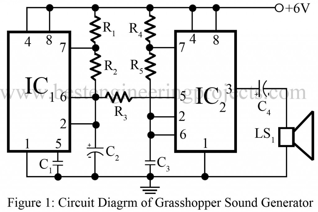
The frequency of IC1 used for modulation is obtained as the sawtooth voltage at pin 6. It is then given to control pin 5 of IC2 to control the frequency of IC2 as stated above. Here, IC1 serves as a low-frequency oscillator whereas IC2 acts as a high-frequency oscillator. The sawtooth voltage at control pin 5 of IC2 is used to drive output audio frequency (3 – 30 KHz) high and low. Because of this, we hear something like the shrill sound of insects (pi-pi sound of grasshopper).
Check out other different sound generators posted on bestengineeringprojects.com
- Machine Sound Generator Using 555 Timer IC
- Multi Sound Generator Circuit
- Wind Sound Generator Using IC 741
- Rain Sound Generator
- Aural Metronome Circuit
PARTS LIST OF GRASSHOPPER SOUND GENERATOR CIRCUIT USING 555 TIMER IC
| Resistor (all ¼-watt, ± 5% Carbon) |
| R1 = 3.3 KΩ
R2, R4, R5 = 10 KΩ R3 = 8.2 KΩ |
| Capacitors |
| C1 = 0.01 µF, 50V (Ceramic Disc)
C2 = 4.7 µF, 10V (Electrolytic Capacitor) C3 = 0.033 µF, 50V (Ceramic Disc) C4 = 220 µF, 25V (Electrolytic Capacitor) |
| Semiconductors |
| IC1, IC2 = NE555 (Timer IC) |
| Miscellaneous |
| L.S. = 8 Ω speaker |
would it be possible to modify this to run it on 9 volts?
No modification is required you can directly connect 9V power supply instead of 6V.
Hi. I would use your sound generator on 1,5 V is it possible ?
Hi, Rodolphe Figuet, A timer IC 555 is used here and its working voltage is between 4.5V to 15V. So 1.5V cannot be used.
Thanx for your reply,
Is another way possible ? Another timer ?
At least you have to use 4.5V in order to use this circuit.
Yes I understood what you meant.
My question was “Is it possible to use another type of timer ?”
Another reference to work properly with a AAA 1,5 battery ?
Sorry for my bad english :)