Gambling is quite fun if played wisely. Due to the fact that rolling of dice can be disturbed and may not be precise, use of dice might not be more appealing. The game can be modernized in the form of electronics circuit. This project, ‘Electronics Gambling Game Circuit’ is the result of such thoughts. This project makes the game more precise and at the same time is much simple and inexpensive. With the fact that any normal individual after gathering basic knowledge from electronics can design this electronics game, this project becomes more fascinating.
Description of Electronic Gambling Game Circuit
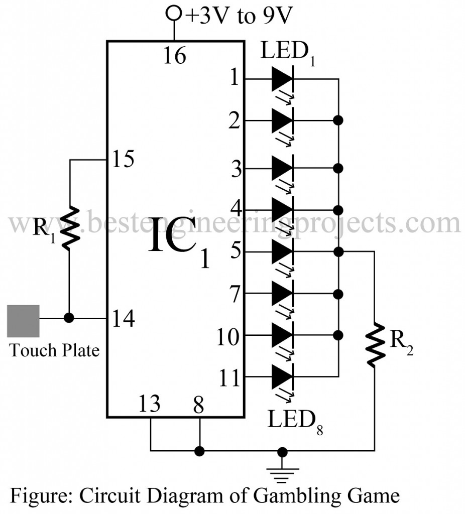
CMOS IC (CD4022), LED and touch plate are the only components require on the course of developing the project ‘Electronic Gambling Game Circuit’. The complete circuit of electronic gambling game is built around CMOS IC (CD4022), which is thus the major component we will use.
To interface user with this electronics circuit, a touch plate is introduced. In this project, this touch plate is used as a switch and is connected to pin 14 and 15 of IC through resistor R1 as shown in circuit diagram. When the player touches the touch plate, the frequency of 50 Hz is obtained in this plate due to our body frequency which then triggers the IC. As a result, all of the eight LEDs connected to this circuit glow. And, as the player removes his/her finger from the touch plate, out of all eight LEDs only one LED remains in ‘on’ state. For simplicity, the touch plate used in this circuit is made as small as possible.
Check out other various Game circuit projects posted in bestengineeringprojects.com
- Pachisi Circuit Game using 555 IC
- Electronics Cricket Project | Game Circuit
- LED Dice Using Arduino
- Hypnotizer Using Arduino
- Electronic Game Circuit | Electronic Pendulum
PARTS LIST OF ELECTRONIC GAMBLING GAME CIRCUIT
| Resistors (all ¼-watt, ± 5% Carbon) |
| R1 = 10 MΩ
R2 = 470 Ω |
| Semiconductors |
| IC1 = CD4022BE (octal counter / divider IC)
LED1 – LED8 = 8 LEDs |
| Miscellaneous |
| Touch plate |
