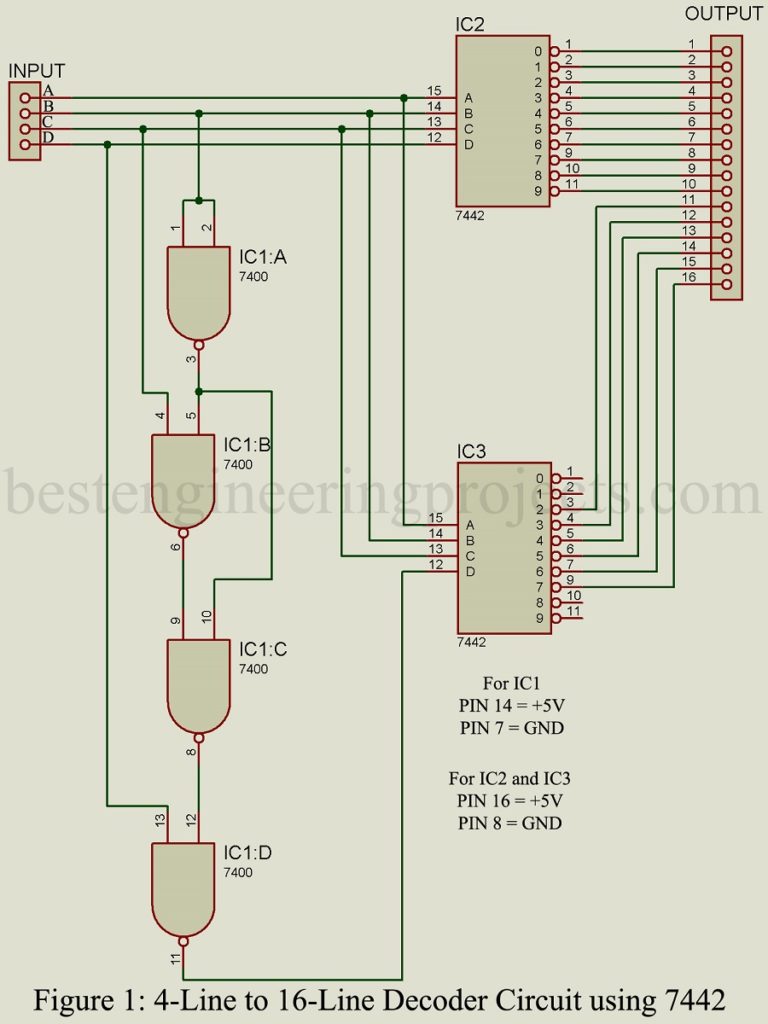
Decoders are essentially an arrangement of logic elements that are combined to change from are digital code to another. The term ‘decoder’ is most frequently used but depending on the point of view, the term ‘encoder’ is equally correct. Figure 1 shows the circuit diagram of a 4-bit, 4-line to 16-line decoder using two 7422 4-line to 10-line decoder IC . The input A, B, C and D can represent any logic function and the output 1 through 16 will then provide the addition or the logic or function of these four inputs.
Here we had designed 4-line to 16-line decoder using two popular TTL IC 7400 and 7422. As we know that 7422 is 4-line to 10-line decoder thus we had used two 7422 IC. IC1 can only decodes the 4-bit input to 10 ten lines 0 through 9 in conventional manner rest 6 line is obtained from IC2. Pin 3 to 7 and 9 pins only goes high rest of pin are always low. IC1 provides driver logic for IC2 and IC3 as shown in circuit diagram.

Application of 4-line to 16-line decoder Circuit using 7442
Decoders are used in digital systems whenever it is necessary to change from one code to another. Specific applications are BCD-TO-DECIMAL, BCD-TO-7-SEGMENT and EXCESS-3 (GRAY) -TO-DECIMAL
TRUTH TABLE | 4-line to 16-line decoder Circuit using 7442
| INPUT | OUTPUT OF IC1 | OUTPUT OF IC2 | |||||||||||||||||
| D | C | B | A | 1 | 2 | 3 | 4 | 5 | 6 | 7 | 9 | 10 | 11 | 3 | 4 | 5 | 6 | 7 | 9 |
| L | L | L | L | L | H | H | H | H | H | H | H | H | H | H | H | H | H | H | H |
| L | L | L | H | H | L | H | H | H | H | H | H | H | H | H | H | H | H | H | H |
| L | L | H | L | H | H | L | H | H | H | H | H | H | H | H | H | H | H | H | H |
| L | L | H | H | H | H | H | L | H | H | H | H | H | H | H | H | H | H | H | H |
| L | H | L | L | H | H | H | H | L | H | H | H | H | H | H | H | H | H | H | H |
| L | H | L | H | H | H | H | H | H | L | H | H | H | H | H | H | H | H | H | H |
| L | H | H | L | H | H | H | H | H | H | L | H | H | H | H | H | H | H | H | H |
| L | H | H | H | H | H | H | H | H | H | H | L | H | H | H | H | H | H | H | H |
| H | L | L | L | H | H | H | H | H | H | H | H | L | H | H | H | H | H | H | H |
| H | L | L | H | H | H | H | H | H | H | H | H | H | L | H | H | H | H | H | H |
| H | L | H | L | H | H | H | H | H | H | H | H | H | H | L | H | H | H | H | H |
| H | L | H | H | H | H | H | H | H | H | H | H | H | H | H | L | H | H | H | H |
| H | H | L | L | H | H | H | H | H | H | H | H | H | H | H | H | L | H | H | H |
| H | H | L | H | H | H | H | H | H | H | H | H | H | H | H | H | H | L | H | H |
| H | H | H | L | H | H | H | H | H | H | H | H | H | H | H | H | H | H | L | H |
| H | H | H | H | H | H | H | H | H | H | H | H | H | H | H | H | H | H | H | L |
PARTS LIST OF 4-LINE TO 16-LINE DECODER CIRCUIT USING 7442
| Semiconductor |
| IC1 = 7400 (transistor–transistor logic (TTL) integrated circuits)
IC2, IC3 = 7442 (Decoder IC) |