Antilogarithmic amplifier is one whose output is antilogarithmic (exponential) of input. Like logarithmic amplifier, antilogarithmic is also a non-linear amplifier.
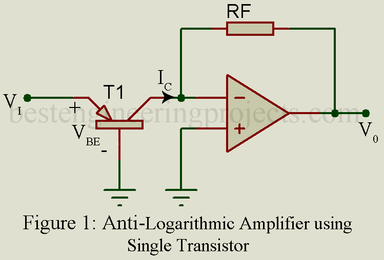
Antilogarithmic Amplifier using Single Transistor
The circuit arrangement for Antilogarithmic amplifier is illustrated in figure 1. Here a general purpose NPN transistor is connected to inverting input of op-amp. A resistor is connected in feedback path. The output is depending upon output current of transistor and feedback resistor.
Now for diagram, output voltage can be written as
 …..(1)
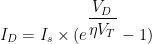
Where, Is = Saturation current
VT = Thermal Voltage

As we know that, 
Thus, we can write 
Now putting the value of collector current of transistor IC in equation 1. The output voltage expression becomes

From the figure we can also conclude that transistor base emitter voltage (VBE) is equivalent input voltage Vi i.e. 
Thus, we can also write output voltage in contest of input voltage Vi

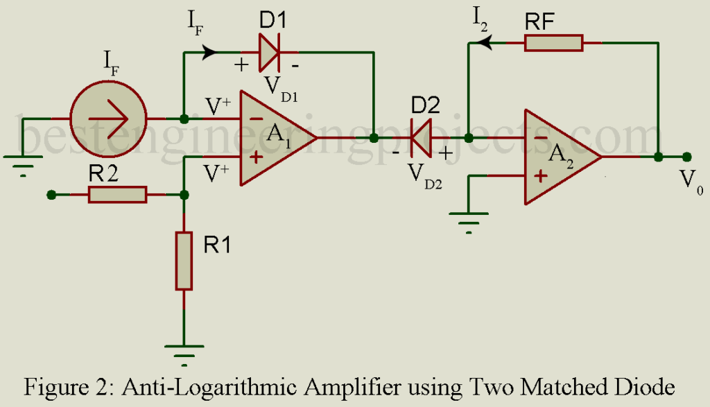
Antilogarithmic Amplifier using Matched Diode
The figure of anti-logarithmic amplifier using matched diode is shown in figure below. Two matched diodes are used here, where one diode (D1) is connected in feedback path and second diode (D2) is connected to inverting input of op-amp (A2) in reverse bias mood as shown in figure 2.
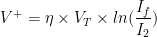
Voltage at inverting pin of op-amp (A1) is potentially equal to voltage at non-inverting input of op-amp i.e. inverting input voltage = non-inverting input voltage = V+ say. Thus, we can write
 ……(2)
……(2)
Now, we can use KVL in order to solve for V+ voltage.

 …..(3)
Now, solving for diode
Where, 
We know that 
Thus, we can write

Output voltage of diode VD can be written as,

Now, we can calculate individual diode voltage i.e. VD1 and VD2.

Assuming both diode and matched thus material constant, thermal voltage of diode and saturation current of diode is also same. Thus, we can write


From equation 3, we can write

Putting the value of I2 in equation V+
 …..(4)
Now from equation 2 and 4 we can write

![V_o = I_f \times R_f \times exp[\dfrac{-V_s}{\eta \times V_T} \times \dfrac{R_1}{R_1 + R_2}]](https://s0.wp.com/latex.php?latex=V_o+%3D+I_f+%5Ctimes+R_f+%5Ctimes+exp%5B%5Cdfrac%7B-V_s%7D%7B%5Ceta+%5Ctimes+V_T%7D+%5Ctimes+%5Cdfrac%7BR_1%7D%7BR_1+%2B+R_2%7D%5D&bg=ffffff&fg=000&s=0&c=20201002)
- Temperature sensitive factor
 can be eliminated by adjusting voltage divider also temperature sensitive in such a way that their effect get can canceled.
 can be eliminated by adjusting voltage divider also temperature sensitive in such a way that their effect get can canceled.
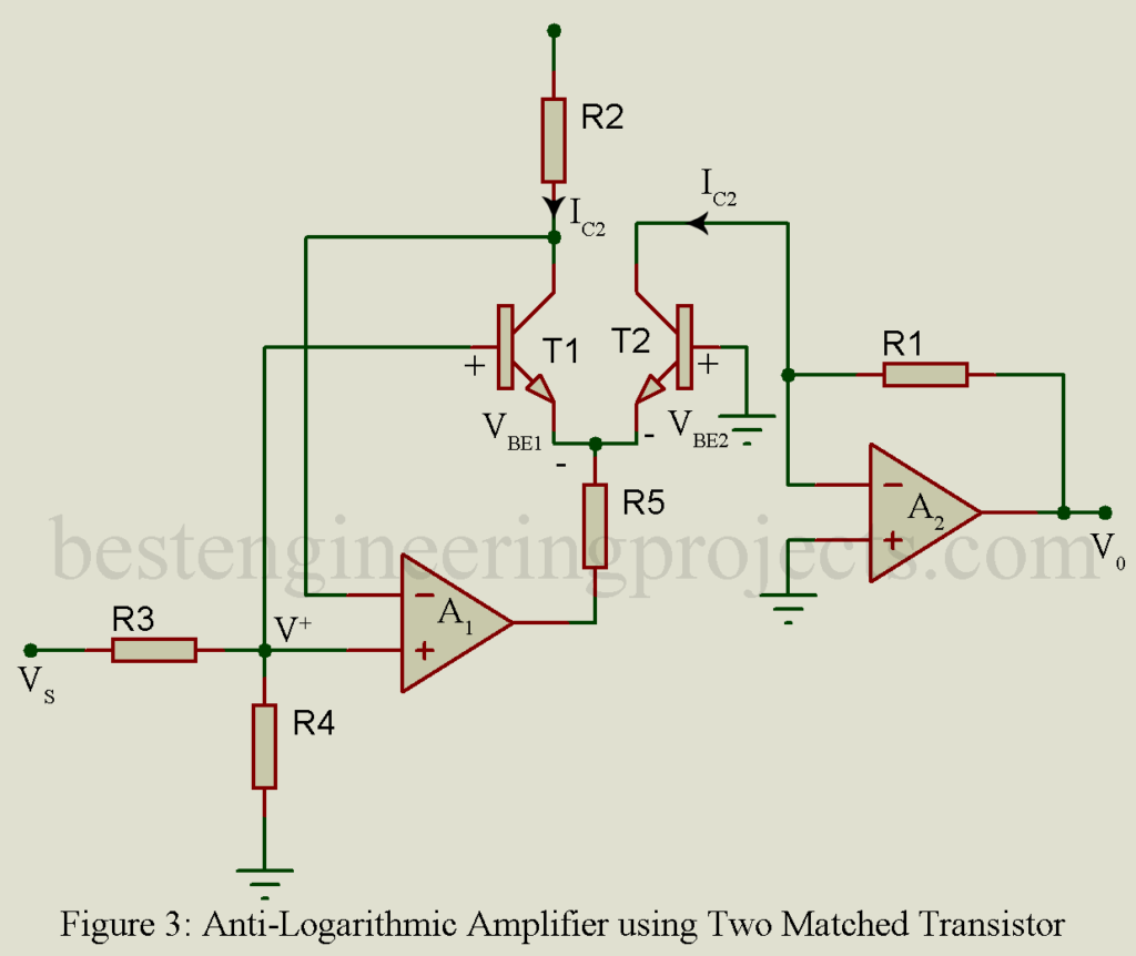
Antilogarithmic Amplifier using Two Matched Transistors
The figure of anti-logarithm amplifier is shown in figure 3. Two matched transistors is used here as shown in figure, where input is given to the non-inverting amplifier pin of first op-amplifier A1.
Now form figure,
 ……(5)
……(5)

 …..(6)
For transistor,
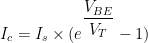
We know that,

Now, we can drive base emitter voltage of each transistor.
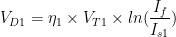
Base emitter voltage of 1st transistor VBE1 can be written as

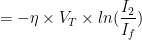
Base emitter voltage of 2nd transistor can be written as

Assuming both transistors are matched. Thus, thermal voltage of 1st transistor will be same to thermal voltage of 2nd transistor and saturation current of 1st transistor will be equal to saturation current of 2nd transistor. i.e.
;
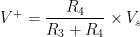
From figure we can write,

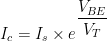
As we know that  is very small. Thus we can write
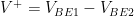
Now we can write,

And 
From equation 6

From equation 1

![V_0 = \dfrac{V_R\times R_1}{R_2} \times exp[-\dfrac{V_s \times R_4}{V_T(R_3 + R4)}]](https://s0.wp.com/latex.php?latex=V_0+%3D+%5Cdfrac%7BV_R%5Ctimes+R_1%7D%7BR_2%7D+%5Ctimes+exp%5B-%5Cdfrac%7BV_s+%5Ctimes+R_4%7D%7BV_T%28R_3+%2B+R4%29%7D%5D&bg=ffffff&fg=000&s=0&c=20201002)
This Anti-logarithmic is temperature sensitive.