Timer IC 555 is one of the most versatile and most used IC because of it’s much more application like PWM amplifier, delay timer, switching circuit, duty cycle selector, clock pulse generator etc. This can also be used in various application like accurate timing, sequential timing, time-delay generation etc. The project Adjustable Dual Timer Circuit using 555 Timer IC is also one of the applications of 555 timer IC. By using this project one can switch two different appliance one after another for adjustable timing (1 Minute to 10 minutes).
Application: This project can be used with another switching circuit like sound detector, light detector in order to switch device for adjustable time. This circuit can also be used as timer circuit in kitchen. House, garden etc.
Circuit Description Adjustable Dual Timer Circuit using 555 Timer IC
Circuit diagram of Dual Timer Circuit using 555 Timer IC is shown in figure 1, built using timer IC 555, resistors, capacitors, diodes and relay for working flawlessly. Both timer IC is configured in monostable low trigger mode. Let’s talk about pin connection of timer IC.
Positive power supply is connected to VCC (Pin 8) and Reset pin (Pin 4) and GND (Pin 1). Trigger pin (Pin 2) is connected to GND through switch SW1 as it is configured in low trigger. Output pin (pin 3) is used to drive Relay. Reset Pin (Pin 4) is also connected to positive power supply. Control voltage pin (pin 5) is connected to ground though a ceramic capacitor as shown in circuit diagram. Threshold pin (pin 6) and discharge pin (pin 7) is sorted together and connected to one end of resistor R (resistor between Vcc and pin 7).
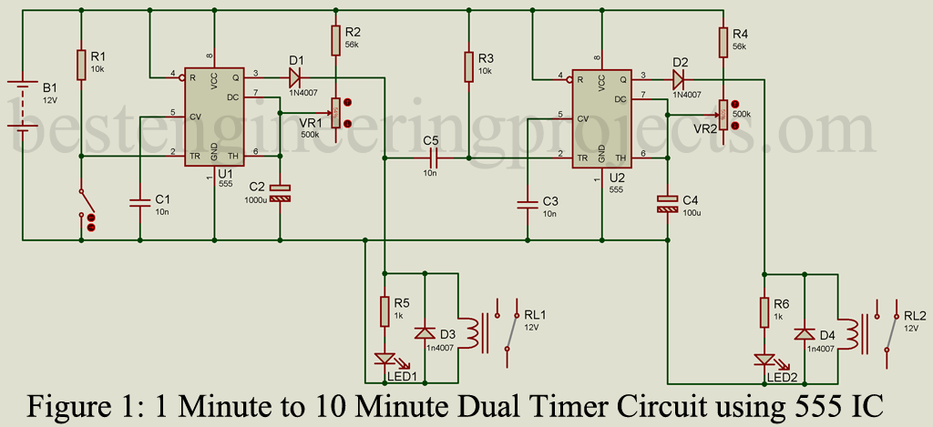
A capacitor is connected between sorted pin (pin 6 and 7) and GND pin as shown in circuit diagram. Diode at output is connected in order to protect the circuit form reverse voltage. A relay switching with LED is connect to output of IC1. Trigger pin (pin 2) of IC2 is also connected to output of IC1 (Pin 3) and rest of circuit is same as first timer.
Working of Adjustable Dual Timer Circuit using 555 Timer IC
When switch SW1 is pressed, pin 2 (Trigger pin) is sorted with ground and triggered. As a result, output from pin 3 become high and energized relay for pre-defined time. This time interval is adjusted using variable resistor VR1.
Mathematical calculation for time delay
Time delay = 1.1 x R x C
Where R = Resistor between Vcc and sorted Pin (pin 6 and 7).
C = Capacitor between shorted pin (pin 6 and 7) and GND.
From above formula we can change time interval wither by changing the value of resistor R and capacitor C. Instead of changing capacitor we are changing the value of resistor because of its availability, cheap and easy to use.
In the circuit below R = R1 + VR1. Minimum value of R = 56K + 0 = 56K and Maximum value of R = 56K + 500K = 556K and C = C3 = 1000uF.
Minimum Time Interval (T1) = 1.1 x 56000 x 1000 x 10-6.
T1 = 61.6 Sec = 1.026 Min.
Maximum Time Interval (T2) = 1.1 x 556000 x 1000 x 10-6
T2 = 611.6 Sec. = 10.19 Min.
In this way we can adjust time interval between 1 minute to 10 minutes by adjusting variable resistor.
Output is used to drive the relay for this time interval. A diode is connected across the coil of relay in order to protect the circuit from fly-back voltage. This output is also connected to trigger pin of IC2 through a ceramic capacitor as shown in circuit diagram. And when the output of IC1 become low, IC2 triggered and rest working of the circuit is same as first timer circuit.
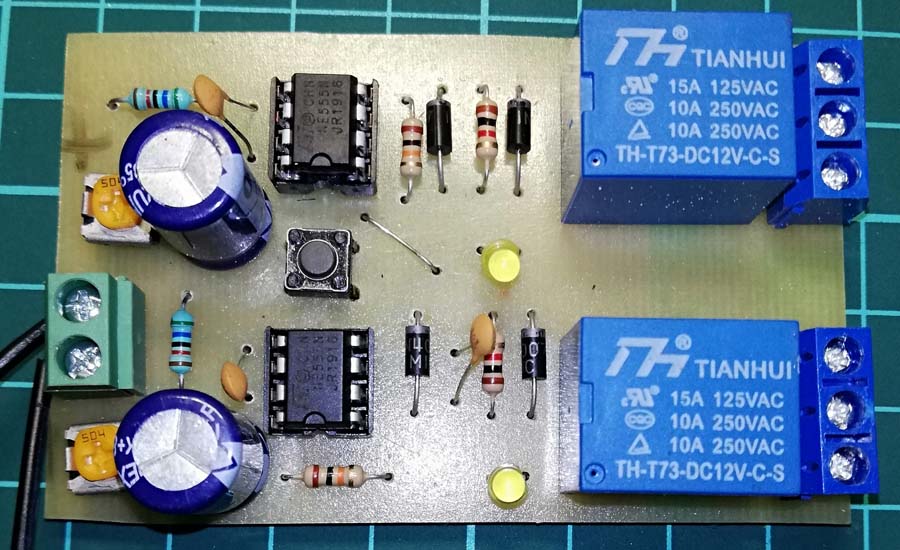 Figure 2: Author Prototype of Dual Timer Circuit
PCB Design:
PCB design of Dual timer is designed using Altium Designer 18. Solder side and component side is shown in figure 3 and 4. A jumper is used as shown in component side in order to make common ground. Download actual size PCB of solder side and component side in PDF format from the link given below.
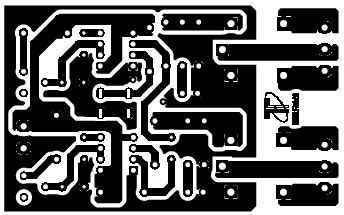
Figure 3: Solder Side PCB
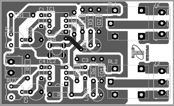 Figure 4: Component Side PCB
Click Here to Download PCB Diagram
Components list
| Resistor (all ¼-watt, ± 5% Carbon Unless Stated Otherwise) |
| R1, R3 = 10KΩ
R2, R4 = 56KΩ R5, R6 = 1 KΩ VR1, VR2 = 500KΩ |
| Capacitor |
| C1, C3, c5 = 10nF (Ceramic Disc)
C2, C4 = 1000uF/16V (Electrolytic Capacitor) |
| Semiconductor |
| U1, U2 = NE555
D1 – D4 = 1N4007 LED1, LED2 = 3mm Led |
| Miscellaneous |
| RL1, RL2 = 12v SPDT 100Ω Relay
SW1 = Push-to-on-switch 12V power supply unit |
Hello,
Nice work with the dual timer. I have a question, I made the circuit and when I gave power to the circuit then sometimes 2nd 555 timer IC triggered however it should only be triggered when the timer of 1st 555 gets over. Kindly tell what can be the possible cause?
Also is this problem related to the value of C5? I have chosen 10nF capacitor, should I increase its value?
Thanks.
Regards,
Asfand
Hello sir my WhatsApp number 918888662533
First time start button after that first relay will run on only 1 minute second relay will on after 3 seconds it will run automatically on 10 minutes please contact