The project posted here is called an automatic voltage stabilizer circuit which solves almost all problems faced in the normally available stabilizer efficiently. With the help of the automatic voltage stabilizer circuit, we can keep the constant voltage at 230V when the voltage goes low as 170V and high as 250V automatically.
The working strategy of the Automatic Voltage Stabilizer Circuit
The working strategy of the circuit is very simple, this circuit energized one relay at a time from 170V AC upwards, and all relays and energized when 230V AC input is reached. Similarly, if supply input voltage decreases gradually from 230V, the relay is de-energized automatically one by one so that the output voltage remains constant at 230V AC.
Various other voltage stabilizers and automatic cutoff units are posted on bestengineeringprojects.com, you may like
- AC Voltage Stabilizer Circuit using 556 IC
- Versatile Auto Cut-off Unit
- Automatic Cut off Power Supply
Circuit Description of Automatic Voltage Stabilizer
The power supply to the circuit is given from the secondary coil of transformer X2. As the voltage between two tappings is 20V, it is directly rectified using a bridge rectifier using diode D1 through D4. The rectified output is further filtered using electrolytic capacitor C1.
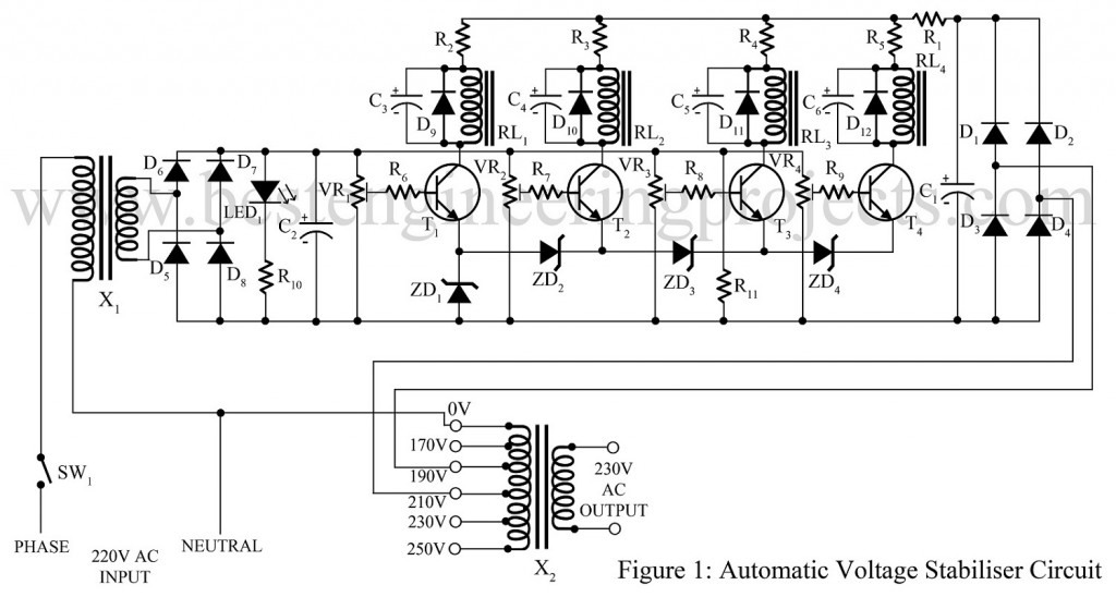

The voltage input from the source is sensed by the transformer X1 and is rectified with the help of a bridge rectifier made from diodes D5 through D8. The rectified output is further filtered by capacitor C2 and given to the base of transistor T1 to T4 through variable resistors VR1 to VR4. For reference voltage, Zener diode ZD1 to ZD4 is used.
PARTS LIST OF AUTOMATIC VOLTAGE STABILIZER CIRCUIT
| Resistor (all ¼-watt, ± 5% Carbon) |
| R1 = 4.7 Ω, 3W
R2, R3 = 100 Ω,0.5W R4, R5 = 56 Ω, 0.5W R6 – R9 = 1 KΩ R10 = 1 KΩ, 0.5W VR1 – VR4 = 20 KΩ Linear |
| Capacitors |
| C1 = 470 µF/40V (Electrolytic Capacitor)
C2 = 100 µF/40V (Electrolytic Capacitor) C3 – C6 = 10 µF/50V (Electrolytic Capacitor) |
| Semiconductors |
| T1 – T5 = SL100 (general purpose, medium power NPN transistor)
D1 – D12 = 1N4007 (Rectifier Diode) ZD1 – ZD4 = 2V, 1 amp. Zener Diode LED1 = Any Color LED |
| Miscellaneous |
| X1 = 230V AC primary to 0-12V, 300mA Secondary
X2 = 230V AC primary to 0-170V, 190V,210V,230V,250V Secondary RL1 – RL4 = 12V, 300 Ω double contact relays SW1 = ON-OFF Switch |
can you tell me what is the purpose of capacitor C3toC6.Thanks
Please sir why the zener diode 2v instead of 12v or is that a mistake
Value of zener diode is 2V.
I WANT TO MAKE A MANUAL STABILIZER. IN WHICH ROTARY CONTROL THE RELAY CONTRACTOR FOR VOLTAGE STAVBILIZTION CONTROL. ON INCREASING VOLTAGE IT AUTOMATICALLY STEP DOWN TO LOW VOLTAGE RELAY.
Hi Ravi, please elaborate your question.
Did you mean “I want to built a stabilizer with automatic and manual facility?”
Please for value to be set using thé variable résistor
Thanks so much. Please how can I calibrate the variable resistors vr1 to vr4 with respect to the supply voltage.
can you give me the ckt ?
Hi, I want to build a automatic stabilizer with relay.
the power of 5000 watts! could you please guide me?