AC Voltage Stabilizer Circuit using 556 IC
Various types of AC voltage stabilizer circuits had already been posted on bestengineeringprojects.com like
The circuit posted here is a cheap, versatile, and high-performance AC voltage stabilizer using dual timer IC 556 IC. The circuit makes use of most of the features of dual timer IC 556, namely, the four voltage level comparators, two high current sourcing/sinking outputs, two discharge transistors, and the ability to provide hysteresis with the help of its internal flip-flops.
Circuits Description and working of AC Voltage Stabilizer Circuit using 556 IC
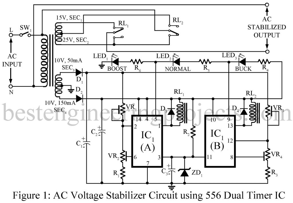
The circuit of the AC voltage stabilizer is built around the very popular dual timer IC 556. The AC mains voltage is given to the primary input of transformer X1. The output of secondary-4 of the transformer X1 as shown in figure 1 is rectified to give power supply to the entire circuit. The output of secondary-3 is rectified to sense the mains voltage level. A zener diode clamps the control inputs to 9V and 4.5V respectively.
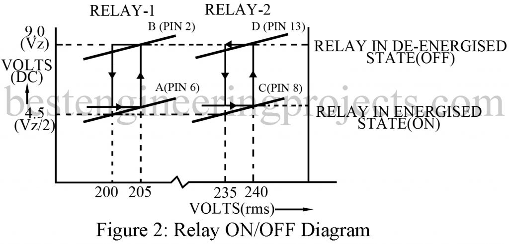
When the mains voltage is between 170V and 205V, the voltage at trigger inputs (pins 6 and 8) is less than 4.5V and hence both the timers are set. At this instance, both relays are in a de-energized position and both secondary winding 1 and 2 of the transformer are in series with the mains supply. Only the BOOST LED is turned on.
As the voltage increased to 205V, the voltage at threshold input (pin 2) reaches 9V, and timer 1 (1/2 556) is reset which further energized relay RL1 which led to appearing the mains voltage at the output. Only NORMAL LED lights up. As for mains voltage increases to 240V, the voltage at pin 13 of IC1 reaches 9V, and timer 2 (1/2 556) is reset which further energized relay RL2, and secondary winding 2 is switched in series-opposition with the mains supply and only the BUCK LED glow.
Working of AC Voltage Stabilizer Circuit using 556 IC
When the input is decreased to 235V, the voltage at trigger input (pin 8) reaches 4.5V, timer 2 is set and relay RL2 is de-energized. When the input is reduced to 200V, the voltage at trigger input (pin 6) reaches 4.5V, and timer 1 is set, de-energizing RL1.
The stabilizer is calibrated to switch the boost and buck secondary’s in series with the mains supply at the appropriate voltage and to provide the hysteresis required to avoid chattering of the relays. A variable supply is used to calibrate the stabilizer. Sliders of preset VR2 and VR4 are kept in extreme positions to keep the trigger and threshold inputs shorted. Calibration is illustrated in table 1.
First preset VR1 is adjusted such that RL1 gets energized at 205V when inputs are increased from zero. Next, preset VR2 is adjusted so that RL1 gets de-energized at 200V when inputs are decreased from 205V. Relay RL2 should get energized at 240V when input is increased from zero. For this preset VR3 is adjusted. Finally, RL2 should get de-energized at 235V when input is decreased from 240V. Preset VR4 is used for this adjustment.
Now the equipment is calibrated and ready for use. Note that the VA rating of the transformer must suit the equipment intended to be protected.
| Table 1: Calibration | ||||
| Mains Input Voltage (V) | Mode | Relay – 1 | Relay – 2 | Output Voltage (V) |
| 170 – 205 | BOOST | OFF | OFF | 200 – 240 |
| 200 – 240 | NORMAL | ON | OFF | 200 – 240 |
| 235 – 270 | BUCK | ON | ON | 209 – 240 |
PARTS LIST OF AC VOLTAGE STABILIZER CIRCUIT USING 556 IC
| Resistor (all ¼-watt, ± 5% Carbon) |
| R1, R3 = 10 KΩ
R2 = 680 Ω R3 – R5 = 1 KΩ VR1, VR3 = 22 KΩ VR2, VR4 = 10 KΩ |
| Capacitors |
| C1, C3 = 47 µF, 25V (Electrolytic Capacitor)
C2 = 470 µF, 25V (Electrolytic Capacitor) |
| Semiconductors |
| IC1 = LM556 (Dual Timer IC)
D1 – D4 = 1N4001 ZD1 = 9V, 250mW zener diode LED1 – LED3 = Three Different Color LED |
| Miscellaneous |
| X1 = 220 primary to 4 secondary transformers
SW1 = ON/OFF Switch RL1, RL2 = 12V, 250 Ω Relay |

