Various types of alarm and sound generator circuit is already published in bestengineeringprojects.com. Now here is a alarm circuit which draws very low quiescent current and also does not need any type of power on off switch because this offers automatic switch-off after fixed time.
Circuit Description of Low Power Alarm with Automatic Timer
The heart of the circuit low power alarm circuit is 4060 IC, which is here configured as timer. The advantage of using IC 4060 (IC1) is the wide music range instead of UM series musical IC. When high going pulse is given to input at pin 12 through capacitor C2 and resistor R2 IC1 starts oscillating. The oscillating frequency is determined by resistor R14 and its value should be chosen according to frequency required, minimum value being 10 KΩ.
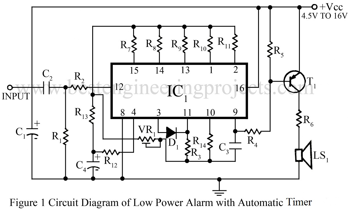
Resistor R14 with R3 and capacitor C3 are frequency determined components of the internal oscillator. When power supply is given pin 3 of IC1 is low and diode D1 is act like reverse-mode hence internal oscillator oscillates. Digital to analog converter circuit is build using resistor R7 through R11 or we can also say voltage divider circuit.
Voltage is applied to the oscillator through VR, oscillator change their oscillating frequency. This voltage is also affected by capacitor C4. This lest pin 3 of IC1 goes high, oscillator switch off since diode D1 becomes forward biased.
The output of IC1 from pin 9 is given to base of transistor T1 base through resistor R4. Transistor T1 is here used as loudspeaker driver. The output from collector of transistor T1 is given to loudspeaker through resistor R6.
Check out other interesting sound generator circuit using timer IC 555 using bestengineeringprojects.com
- Sound Operated Intruder Alarm with Flash
- Fire Alarm Using Thermistor and NE555
- Machine Sound Generator Using 555 Timer IC
- Beeper for Automobile Flasher Using 555
- Grasshopper Sound Generator Circuit using 555 Timer IC
PARTS LIST OF LOW POWER ALARM WITH AUTOMATIC TIMER
|
Resistor (all ¼-watt, ± 5% Carbon) |
|
R1 – R3, R13 = 100 KΩ R4, R12 = 47 KΩ R5 = 35 KΩ R6 = 100Ω R7 = 2.2 KΩ R8 = 1.5 KΩ R9, R14 = 10 KΩ R10 = 8.2 KΩ R11 = 6.8 KΩ VR1 = 1MΩ |
|
Capacitors |
|
C1 = 10 µF, 16V (Electrolytic Capacitor) C2 = 0.1 µF (Ceramic Disc) C3 = 0.01 µF (Ceramic Disc) C4 = 1 µF, 16V (Electrolytic Capacitor) |
|
Semiconductors |
|
IC1 = CD4060 (Counter IC) T1 = SL100B (Medium power silicon NPN Transistor) D1 = 1N4148 (Small Signal Diode) |
|
Miscellaneous |
|
LS1 = 8Ω Loud Speaker |