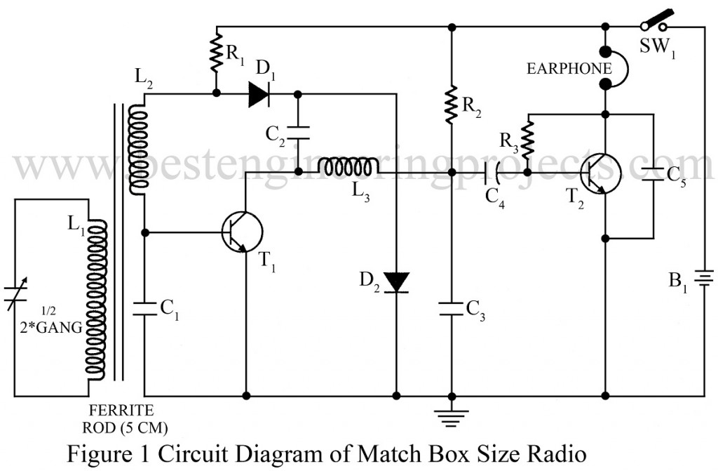
This small-size radio published is very interesting and useful for students. Using the circuit Smallest Radio Circuit Using Two Transistors described here, one can make a very compact MW radio receiver. This circuit uses only two transistors and a few passive components, as all the components can be easily placed in a small matchbox-size cabinet.
Smallest Radio Circuit Using Two Transistors
Coil L1 consists of 100 turns of 40 SWG insulated wire. Wind L2 over L1, which is 10 turns of the same wire. For L3, wind 56 SWG (approximately) over an ordinary IFT former without using a core and metal cover. Counting turns is not necessary. Wind the wire completed over a former pulley. It may be fixed on the PCB using wax.
After making all connections, switch on SW1 and plug the earphone into your ear. Now rotate the gang’s knob slowly till you can hear the program from the local Mw station. This circuit does not need an aerial. Playing the unit near the main wiring is also not necessary. If a clear result is not obtained, check the connection once again. Adjust the antenna coil over the ferrite rod if they are all right. This circuit will work very well with a miniature speaker.
Parts List of Smallest Radio Circuit Using Two Transistors
|
Resistor (all ¼-watt, ± 5% Carbon) |
|
R1 = 56 KΩ R2 = 680 Ω R3 = 10 KΩ |
|
Capacitors |
|
C1, C3 = 0.0047 µF (Ceramic Disc) C2 = 220 Pf (Ceramic Disc) C4 = 10 µF, 16V (Electrolytic Capacitor) C5 = 0.01 µF (Ceramic Disc) C6 = ½ 2* Gang capacitor |
|
Semiconductors |
|
D1 = 1N34/OA79 (Germanium Diode) D2 = 1N34 (Germanium Diode) T1 = BF194 (Silicon NPN Transistor) T2 = BC148 (Silicon NPN Transistor) |
|
Miscellaneous |
|
L1 = 100 Turns of 42 SWG over ferrite L2 = 10 Turns of 42 SWG over L1 L3 = Wound 56 SWG thin insulated wire uniformly over IFT center coil SW1 = ON-Off Switch Earphone B1 = 1.5V Battery |

I would like to know what is the Inductance Value of L3 Coil in this Radio.This is because I want to use a Fixed Resistor Type inductor instead of the Wire Bound 56 SWG Wire Inductor Choke.
Also kindly advise if I want to make an Wire bound Inductor Choke using a 56 SWG Enameled copper wire, then what is the length of the 56 SWG Copper wire that is to be used and should I wind it on a Small size Ferrite Bead or any insulated core.
Looking forward for an early advise…
Thanks :)
As i mentioned already in above article, counting of turns is not necessary. And if you want to used fixed type inductor, then simply check various inductor. but i preferred you 1mH.
Any one tested this circuit? Is it working?
Audio functionality is ok, but not getting any radio signals.
I wired this circuit and getting BF194 collector voltage of 0.42V and base voltage of 0.74V with ref. ground. It is ok.
Can anyone help me.