If we search for fire alarm circuits on the internet, we can find a long list of such circuits. Most of those circuits are quite expensive and also the components may not be easily available. So, here we have presented a simple and inexpensive project of ‘fire alarm using thermistor and NE555’. Where a thermistor is the main component and is used as a temperature sensor of the fire alarm. Talking about the working principle of a thermistor, it works in the same way a normal LDR would work i.e. change resistance with a change in heat whereas LDR changes resistance with a change in the amount of light falling on it.
Circuit Description of Fire Alarm Using Thermistor and NE555: –
The whole circuit of fire alarm using thermistor is built and fabricated around thermistor (TH1) and timer IC (IC1) with its driver transistor. The timer IC (IC1) used in this circuit is an astable multivibrator oscillator used to oscillate in the audio frequency band. The two transistors T1 and T2 are used to drive the timer IC (IC1). The output from pin 3 of IC1 is fed to the loudspeaker through transistor T3 to generate sound. The value of resistor (R5 and R6) and capacitor (C2) used in this circuit determines the frequency of IC2.
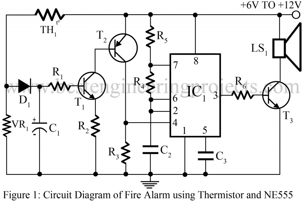
When the thermistor (TH1) becomes hot, the low resistance path of extended positive voltage is provided to the base of the transistor. Further collector of transistor T1 is connected to the base of transistor T2 which provides a positive voltage to reset pin 4 of IC1.’Fire alarm using thermistor circuit works on a wide range of input power supply voltage i.e. 6v to 12V. This property makes this project more secure.
Check out various other interesting alarm projects posted on bestengineeringprojects.com
- Earth Quake Alarm
- Door Ajar Alarm Circuit
- Sound Operated Intruder Alarm with Flash
- Alarm Circuit for Clocks
PARTS LIST OF FIRE ALARM USING THERMISTOR AND NE555
| Resistors (all ¼-watt, ± 5% Carbon) |
| VR1 = 10 K Ω
R3, R7, R8 = 470 Ω R2 = 33 K Ω R4 = 560 Ω R5 = 47 KΩ R6 = 2.2 KΩ |
| Capacitors |
| C1 = 10 µF, 16V (Electrolytic Capacitor)
C2 = 0.04 µF (Ceramic Disc) C3 = 0.01 µF (Ceramic Disc) |
| Semiconductors |
| IC1 = NE555 (timer IC)
T1 = BC548 (general-purpose NPN bipolar junction transistor) T2 = BC558 (general purpose PNP transistor) T3 = SL100B or any Medium power general purpose NPN transistor like: 2N4922, 2N4921, 2N4238, FCX1053A D1 = 1N4001 (Rectifier Diode) |
| Miscellaneous |
| TH1 = Thermistor 10 KΩ
LS1 = 8 Ω, 1W speaker |