Interfacing DS18B20 Temperature Sensor with Arduino: This article is all about DS18B20 and its interfacing with arduino. DS18B20 comes in two variants: Normal and waterproof version. Normal version is available TO-92 and uSOP. Let’s start with introduction.
Description of DS18B20
It is digital programmable temperature sensor based on one wire communication i.e. it requires only data line and common GND. Power supply is optional because this sensor can drain require power supply from data line and this mode called parasite mode.
DS18B20 can provide different temperature resolution is 0.50C, 0.250C, 0.1250C and 0.06250C corresponding to 9-bit, 10-bit, 11-bit and 12-bit respectively. So, accuracy depends upon bit we are using.
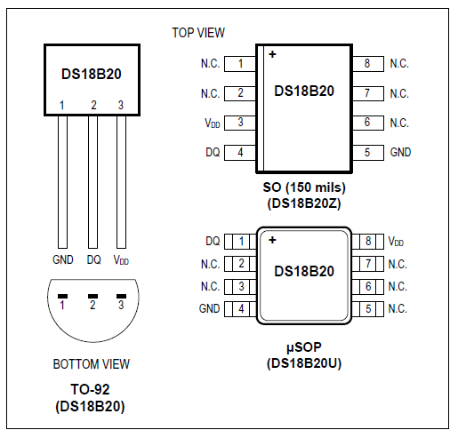 Figure: pin diagram of DS18B20
As DS18B20 work on wire protocol so a small pull up resistor is required because it linked to bus through an open-drain port or 3-state. You can also use multiple sensors over single line because of its 64-bit serial code. So, virtually you can connect unlimited number of DS18B20 sensor over a single digital pin of arduino.
DS18B20 also have in built alarm signaling i.e. if alarm condition exists, alarm flag is set and this value is update after every measurement. Any controller (master device, let’s say arduino nano) can check the flag using proper command.
Time for temperature reading and conversion:
The time require for temperature measurement and conversion of this sensor depends upon resolution we are using. As resolution increases, measurement and conversion time also increases as shown in table below.
| Register to select resolution | Resolution Bits | Max. Conversion Time | |
| R1 | R0 | ||
| 0 | 0 | 9 | 93.75 mS |
| 0 | 1 | 10 | 187.5 mS |
| 1 | 0 | 11 | 375 mS |
| 1 | 1 | 12 | 750 mS |
Summery of Specification and features
- Work on one wire communication protocol
- Two mode of power supply
- External power supply mode: Power supply voltage 3.0V to 5.5V.
- Parasite mode: No external power supply needed
- Measuring Temperature range: -550C to + 1250C
- Accuracy +/-0.50C
- Resolution: 0.06250C to 0.50
Component required for Interfacing DS18B20 Temperature Sensor with Arduino
1 x Arduino Nano
1 x DS18B20 temperature sensor
1 x I2C 16x2LCD
1 x 4.7K Resistor
Jumper wire
Breadboard
Circuit description of Interfacing DS18B20 Temperature Sensor with Arduino
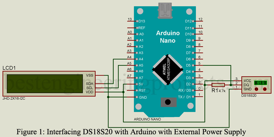
The circuit of Interfacing DS18B20 Temperature Sensor with Arduino is shown in figure below. An I2C LCD is connected to arduino I2C pin which display the temperature. According to 1-wire bus protocol, a 5k resistor is required which make idle state for 1-wire bus is high. So, a 4.7k (nearest resistor) is connected to DQ pin to power supply pin.
There are two way to power DS13B20
Using External power supply: VDD pin is connected to 5V of arduino, where ground pin is connected to GND pin of arduino. Data line DQ is connected to D5 of arduino with a pull up as shown in circuit diagram.
Without using external power supply (parasite mode): All the connection is same except VDD pin of sensor is sorted to ground as shown in figure below.
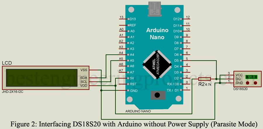
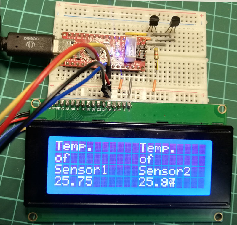
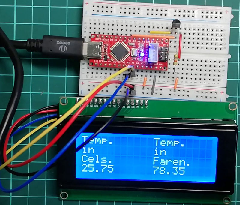 Figure: Author Prototype of Interfacing DS18B20 Sensor with Arduino
Software Code:
Before going to software section, you have to download two different libraries.
For downloading library go to Sketch>>Include Library>>Manage Libraries and then search for “onewire” and install OneWire by Jim Studt.
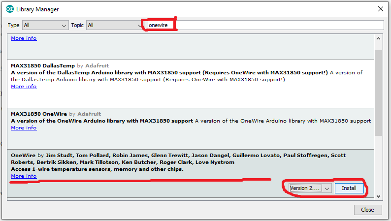 Figure: Installing OneWire Library
Now again search for Dallas and install DallasTemperature by Miles Burton
 Figure: Installing Dallas Temperature Sensor Library
After installing these two libraries upload the sketch to your arduino board. The sketch is based on Dallas temperature library example.
|
1 2 3 4 5 6 7 8 9 10 11 12 13 14 15 16 17 18 19 20 21 22 23 24 25 26 27 28 29 30 31 32 33 34 35 36 37 38 39 40 41 42 43 44 45 46 47 48 49 50 51 52 53 54 55 56 57 58 59 60 61 62 63 64 65 66 |
// Include the libraries we need #include <LiquidCrystal_I2C.h> #include <OneWire.h> #include <DallasTemperature.h> // Data wire is plugged into port 2 on the Arduino #define ONE_WIRE_BUS 5 // Setup a oneWire instance to communicate with any OneWire devices (not just Maxim/Dallas temperature ICs) OneWire oneWire(ONE_WIRE_BUS); // Pass our oneWire reference to Dallas Temperature. DallasTemperature sensors(&oneWire); /* * The setup function. We only start the sensors here */ LiquidCrystal_I2C lcd(0x27,20,4); // set the LCD address to 0x27 for a 16 chars and 2 line display void setup(void) { // start serial port lcd.init(); // initialize the lcd // Print a message to the LCD. lcd.backlight(); lcd.setCursor(0,0); lcd.print("Dallas Temperature"); lcd.setCursor(0,1); lcd.print("DS18B20 Sensor"); lcd.setCursor(0, 2); lcd.print("Demo"); // Start up the library sensors.begin(); delay(3000); lcd.clear(); } /* * Main function, get and show the temperature */ void loop(void) { // call sensors.requestTemperatures() to issue a global temperature // request to all devices on the bus sensors.requestTemperatures(); // Send the command to get temperatures lcd.setCursor(0,0); lcd.print("Temp."); lcd.setCursor(11,0); lcd.print("Temp."); lcd.setCursor(0,1); lcd.print("in"); lcd.setCursor(11,1); lcd.print("in"); lcd.setCursor(0,2); lcd.print("Cels."); lcd.setCursor(11,2); lcd.print("Faren."); lcd.setCursor(0,3); lcd.print(sensors.getTempCByIndex(0)); lcd.setCursor(11,3); lcd.print(sensors.getTempFByIndex(0)); delay(1000); } |
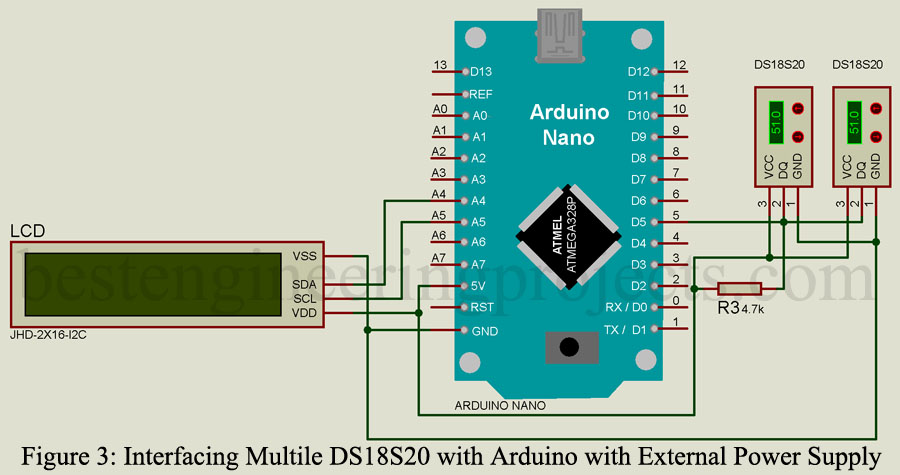
Interfacing Multiple DS18B20 to Arduino
Interfacing of multiple DS18B20 is simple as shown in circuit diagram below. All sensor are connected in parallel to each other i.e. VCC of all sensors are sorted together, GND of all sensors are sorted together and Data pin of all sensors are sorted together as show in circuit below.
Software Code:
|
1 2 3 4 5 6 7 8 9 10 11 12 13 14 15 16 17 18 19 20 21 22 23 24 25 26 27 28 29 30 31 32 33 34 35 36 37 38 39 40 41 42 43 44 45 46 47 48 49 50 51 52 53 54 55 56 57 58 59 60 61 62 63 64 65 66 67 68 69 70 71 72 73 74 75 76 77 78 79 80 81 82 83 84 85 |
#include <LiquidCrystal_I2C.h> #include <OneWire.h> #include <DallasTemperature.h> LiquidCrystal_I2C lcd(0x27,20,4); // set the LCD address to 0x27 for a 20 chars and 4 line display* // Data wire is plugged into port 4 on the Arduino #define ONE_WIRE_BUS 5 // Setup a oneWire instance to communicate with any OneWire devices (not just Maxim/Dallas temperature ICs) OneWire oneWire(ONE_WIRE_BUS); // Pass our oneWire reference to Dallas Temperature. DallasTemperature sensors(&oneWire); int numberOfDevices; // Number of temperature devices found float temC1, temC2; DeviceAddress tempDeviceAddress; // We'll use this variable to store a found device address void setup(void) { sensors.begin(); // start serial port lcd.init(); // initialize the lcd // Print a message to the LCD. lcd.backlight(); lcd.setCursor(0,0); lcd.print("Dallas Temperature"); lcd.setCursor(0,1); lcd.print("DS18B20 Sensor"); lcd.setCursor(0, 2); lcd.print("Demo"); delay(3000); // Grab a count of devices on the wire numberOfDevices = sensors.getDeviceCount(); lcd.clear(); lcd.setCursor(0,0); lcd.print("No. of Sensors"); lcd.setCursor(0,1); lcd.print(numberOfDevices); lcd.setCursor(3,1); lcd.print("Devices"); delay(3000); lcd.clear(); } void loop(void) { sensors.requestTemperatures(); // Send the command to get temperatures // Loop through each device, print out temperature data for(int i=0;i<numberOfDevices; i++) { // Search the wire for address if(sensors.getAddress(tempDeviceAddress, i)){ float tempC = sensors.getTempC(tempDeviceAddress); if(i==0) { temC1 = tempC; } if(i==1) { temC2 = tempC; } } } lcd.setCursor(0,0); lcd.print("Temp."); lcd.setCursor(11,0); lcd.print("Temp."); lcd.setCursor(0,1); lcd.print("of"); lcd.setCursor(11,1); lcd.print("of"); lcd.setCursor(0,2); lcd.print("Sensor1"); lcd.setCursor(11,2); lcd.print("Sensor2"); lcd.setCursor(0,3); lcd.print(temC1); lcd.setCursor(11,3); lcd.print(temC2); delay(5000); } |