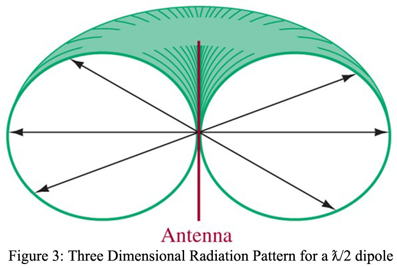
A Hertz Antenna Impedance value may be specified for a half-wave antenna thus constructed. Generally, the impedance at the ends is maximum, while that at the input is minimal. Consequently, the impedance value varies from a minimum value at the generator to a maximum value at the open ends. An impedance curve for the half-wave antenna is shown in Figure 1. Notice that the line has different impedance values for different points along its length. The impedance values for half-wave antennas vary from about  at the open ends to
  at the source ends.
Radiation and Induction Field | Hertz Antenna Impedance
Feeding the Hertz antenna at the center results in an input impedance that is purely resistive and equal to . Recall that with an open-circuited  transmission line the input impedance was
  , and it could therefore not absorb power. By spreading the open transmission line out into a Hertz antenna its input impedance has taken on a finite resistive value. It can now absorb the power, but the question is, how? The answer is that it can now efficiently accept electrical energy and radiate it into space as electromagnetic waves.
While the mechanisms of launching a wave from a current-carrying wire are not fully understood, the fields surrounding the antenna do not collapse their energy back into the antenna but rather radiate it out into space. This radiated field is appropriately termed the radiation field. Antennas also have an induction field associated with them. It is the portion of field energy that does collapse back into the antenna and is therefore limited to the zone immediately surrounding the antenna. Its effect becomes negligible at a distance more than about one-half wavelength from the antenna.
Radiation Pattern
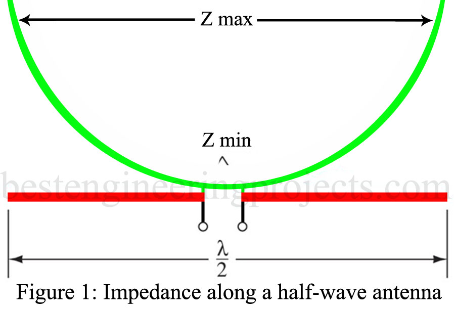
The radiation pattern for the Hertz antenna is shown in Figure 2(a). A radiation pattern is an indication of radiated field strength around the antenna. The pattern is shown in Figure 2(a) shows that maximum field strength for the dipole occurs at right angles to the antenna, while virtually zero energy is launched “off the ends.” We considered an isotropic source of waves. Its radiation pattern is spherical, or as shown in two dimensions [Figure 2(b)], it is circular or omnidirectional. The Hertz antenna is termed directional in that it concentrates energy in certain directions at the expense of lower energy in other directions.
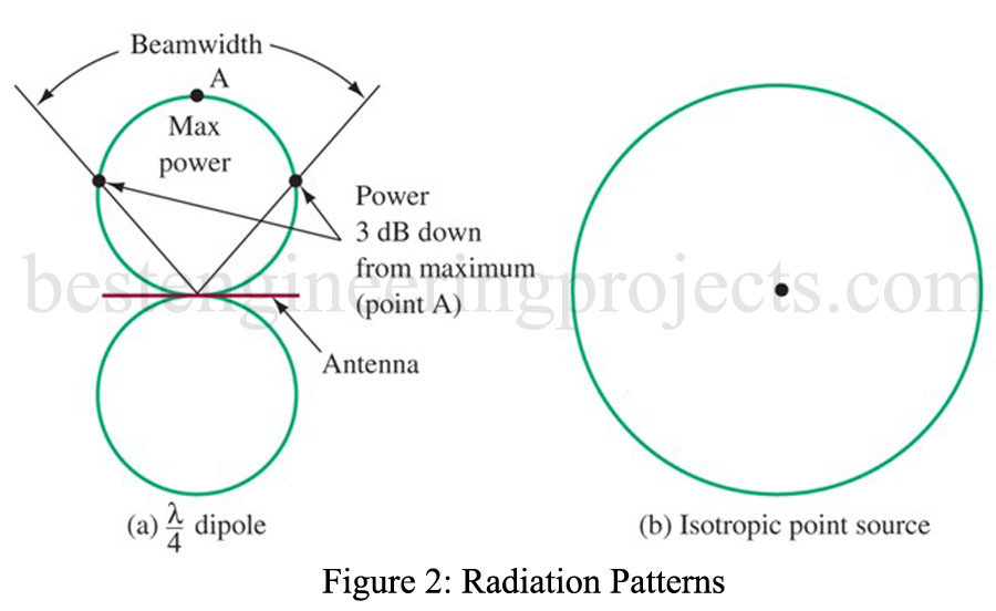
Another important concept is an antenna’s beamwidth. It is the angular separation between the half-power points on its radiation pattern. It is shown for the dipole in Figure 2(a). A three-dimensional radiation pattern crosssection for a vertically polarized dipole is shown in Figure 3. As can be seen, it is a doughnut-shaped pattern. If the antenna were mounted close to the ground, the pattern would be altered somewhat by the effects of ground reflected waves.