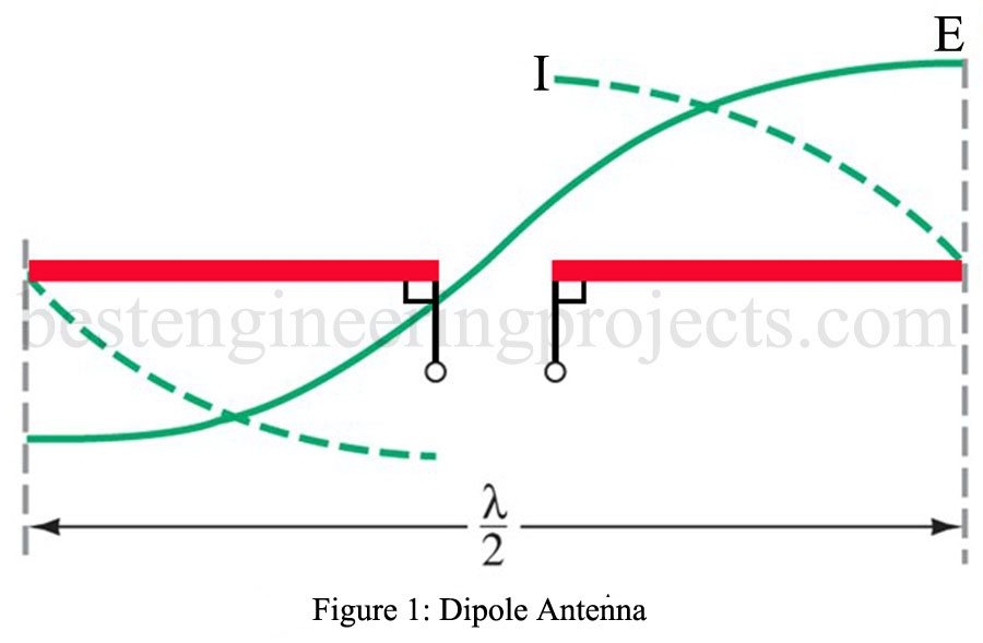
 The hertz antenna is also called a dipole antenna. The Hertz antenna has gain concerning the theoretical isotropic radiator. Dipole Antenna gain is different from amplifier gain since feeding 50 W into a dipole does not result in more than 50 W of radiated field energy. It is, instead, a gain relative to a reference antenna. The dipole, therefore, has a gain relative to the isotropic radiator in a certain direction. The Hertz antenna has a 2.15-dB gain (at right angles to the antenna) as compared to an isotropic radiator.
However, since a perfect isotropic radiator cannot be practically realized, the  dipole antenna is sometimes taken as the standard reference to which all other antennas are compared concerning their gain. When the gain of an antenna is multiplied by its power input, the result is termed its effective radiated power (ERP). For instance, an antenna with a gain of 7 and fed with 1 kW has an ERP of 7 kW.
An antenna whose gain is provided concerning an isotropic radiator is often expressed as dBi. In other words, the dipole antenna gain can be expressed as 2.15 dBi. If an antenna’s gain is given in decibels concerning a dipole, it is expressed as dBi. This occurs somewhat less often than dBi in antenna literature. The gain of an antenna in dBi is 2.15 dB more than when expressed in dBd. Thus, an antenna with a gain of 3 dBd has a gain of 5.15 dBi (3 dB + 2.15 dB).
The amount of power received by an antenna through free space can be predicted by the following:
The formula for Dipole Antenna Gain
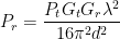
where Pr = power received (W)
Pt = power transmitted (W)
Gt = transmitting antenna gain (ratio, not dB) compared to isotropic radiator
Gr = receiving antenna gain (ratio, not dB) compared to isotropic radiator
 = wavelength (m)
d = distance between antennas (m)
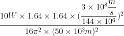
EXAMPLE 1: Two dipoles are separated by 50 km. They are “aligned” for optimum reception. The transmitter feeds its antenna with 10 W at 144 MHz. Calculate the power received.
SOLUTION
The two dipoles have a gain of 2.15 dB. That translates into a gain ratio of  2.15 dB = 1.64.
= 
= 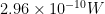
The received signal in Ex. 14-1 would provide a voltage of  into a matched
  receiver system
  ,
,  . This is a relatively strong signal since receivers can often provide a usable output with less than a
  signal.