The entire circuit of the ‘Electric guitar preamp circuit’ is divided into small sections to ensure simplicity and easy understanding of the project. The first section comprises a single transistor that serves as a common-emitter amplifier.
Be it in melodious songs or in rock songs, the guitar is an inseparable part of music in today’s world. To extend the level of sound such that it can be heard by every individual in a mass, amplifier circuits are extensively incorporated into the music system. And this circuit represents a similar concept. The project is thus named as ‘Electric guitar preamp circuit’. The circuit takes any standard guitar pickup as input. It provides two distinct output signals.
Description of Electric Guitar Preamp Circuit:-
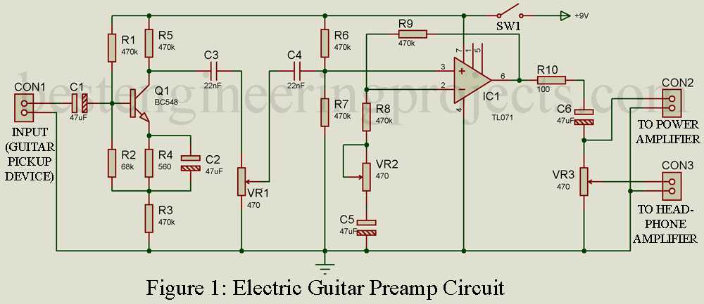
The use of pickup attached to the headstock to extract signals from the guitar is a common practice and a circuit diagram for the same is shown in figure 1. Generally, a transducer on one end and a jack on the next end constitute a pickup device. The jack on the other side is interfaced with the power amplifier system by further plugging it into a pre-amplifier circuit.
The mechanical vibrations produced from stringed instruments such as guitar or violin are recorded by the pickup device. This device is also responsible to transform those vibrations eventually into electrical signals which can later be subjected to an audio amplifier for proper amplification. Mostly this device is mounted on the body of the instrument itself; however, it can also be fixed to the bridge, neck, pickguard, or headstock.
It offers degenerative feedback in the emitter terminal of the transistor and a boot-strapped bias divider is fixed to secure optimal input impedance value. As per the components used in this circuit and with careful calculations, the input impedance value was found to be above 50 kilo-ohms and the peak output voltage was observed to be near 2V RMS. To avoid the distortion level or reduce it to a negligible value, a Master-level-control potentiometer VR1 should be incorporated in the circuit.
The pre-amplifier receives input from the pickup device through the J1 (jack 1) terminal. The signal goes through buffering and then the op-amp circuit wired around IC TL071 (IC1) processes that signal. Preset VR2 is used to adjust the gain of the circuit. The circuit ‘Electric guitar preamp circuit’ has both master and slave control. Master signal output is obtained at the RCA socket J2 (jack 2) terminal and socket J3 (jack 3) acts as a slave.
Usually, the signal from J2 is preferred over J3 to supply as input to the power amplifier system or sound mixer. But, this doesn’t mean that the output signal from J3 is of no use, it is employed to drive a standard headphone amplifier. Another potentiometer VR3 adjusts the slave output signal level at J3.
The circuit ‘Electric guitar preamp circuit’ is set up in a metallic case. The components; VR1 and VR3 should be the same type as the metallic enclosure. The case and the enclosure must be grounded to avoid hum. A 9V regulated DC power supply is the vital portion of this circuit. And, if that is not available, a standard 9V alkaline manganese battery can also be used to power the circuit. To connect or disconnect the supply to the circuit a switch SW1 is used.

Figure 2: Author Prototype
PCB Design of Electric guitar preamp circuit
The solder side and component side PCB diagrams are shown in the figure below. Audio cable connector and switch should be connected to the wall of the box.
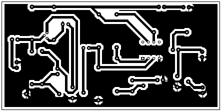 Figure 3: solder side PCB diagram of guitar pre amplifier
 Figure 4: component side pcb diagram of guitar pre amplifier
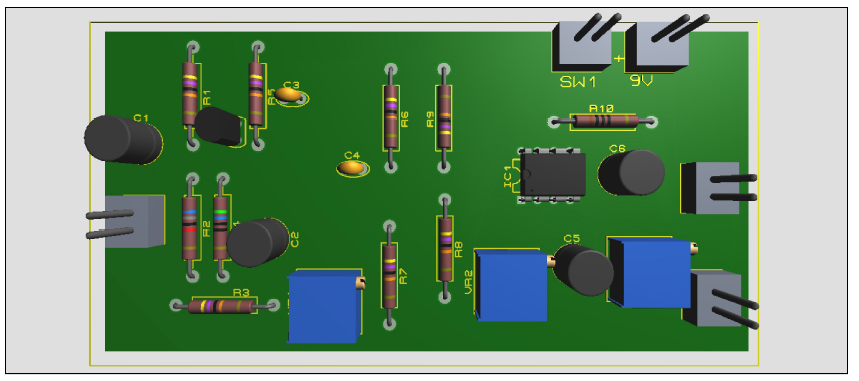 Figure 5: 3D prototype of PCB of guitar pre amplifier
PARTS LIST OF ELECTRIC GUITAR PREAMP CIRCUIT
| Resistors (all ¼-watt, ± 5% Carbon) |
| R1 = 470 KΩ
R2 = 68 KΩ R3 = 220 Ω R4 = 560 Ω R5, R9 = 10 KΩ R6, R7 = 1 MΩ R8 = 470 Ω R10 = 100Ω VR1 = 470 Ω VR2 = 50 KΩ VR3 = 10 KΩ |
| Capacitors |
| C1, C6 = 100 µF/25V (Electrolytic Capacitor)
C2, C5 = 47 µF/25V (Electrolytic Capacitor) C3 = 470 nF (Ceramic Disc) C4 = 22 nF (Ceramic Disc) |
| Semiconductors |
| IC1 = TL071 (Audio Pre-amplifer IC)
T1 = BC548 (general-purpose NPN bipolar junction transistor) |
| Miscellaneous |
| SW1 = ON/OFF Switch
Three audio jack (J1, J2, and J3) |
Various other projects you may like:
- Tone Control for Guitar Amplifier Using 741
- Fuzz effect box for Guitarists
- Guitar Amplifier | Convert Hawain Guitar to an Electric Guitar